background image


Mounting and connection 


4.6 Connecting a programming device 

Carrier controller 
Operating Instructions, 09/2013, A5E03474162-02 

29


4.6.2


Connecting functional ground 

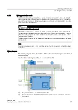
Make allowances for equipotential requirements when connecting a programming device or 

Industry PC. 

Potential differences 

Potential differences may develop between distributed plant parts. Potential differences can 

cause high equalizing currents on the data cables and thus interfere with data transmission 

or damage electronic components. Equalizing currents can develop if the cable shielding is 

terminated at both ends and grounded to different parts of the system.  
Differences in potential can develop when a system is connected to different mains. 

General requirements of equipotential bonding 

You must reduce potential differences to the possible minimum by installing equipotential 

conductors to ensure proper functioning of the respective electronic components. For this 

reason, observe the following rules when installing the equipotential bonding circuit: 


The effectiveness of equipotential bonding increases proportionally with lower impedance 

or greater cross-section of the equipotential bonding conductor. 


If two plant components are interconnected by means of shielded data cables and their 

shielding is grounded at both ends, the impedance of the additionally installed 

equipotential bonding conductor may not exceed 10 % of the shielding impedance. 


The cross-section of an equipotential bonding conductor must be of sufficient size to cope 

with the maximum equipotential current. 
In practical life, equipotential bonding conductors with a minimum cross-section of 

16 mm² are generally accepted for the interconnection between control cabinets or with 

grounding busbars. 


Use equipotential bonding conductors made of copper or galvanized steel. 
Interconnect the equipotential bonding conductors and the earth rod/protective conductor 

on a large surface and protect these against corrosion. 


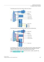
Use a suitable cable clamp to bond the shielding of the data cable flush to the 

equipotential busbar. Keep the length of cable between the HMI device and the 

equipotential busbar as short as possible. 


Route the equipotential bonding conductors and data cables in parallel and with minimum 

clearance between them. 

Summary of Contents for 6ES7212-0AA50-0AA0

Page 1: ..._________________ ___________________ ___________________ SIMATIC EMS400S Carrier controller Operating Instructions 09 2013 A5E03474162 02 Preface Overview 1 Functional description 2 Safety instructions 3 Mounting and connection 4 Operator controls and displays 5 Maintenance and repairs 6 Technical specifications 7 Appendix A Datasheet Live ...

Page 2: ... only by personnel qualified for the specific task in accordance with the relevant documentation in particular its warning notices and safety instructions Qualified personnel are those who based on their training and experience are capable of identifying risks and avoiding potential hazards when working with these products systems Proper use of Siemens products Note the following WARNING Siemens p...

Page 3: ...nstructions are intended for Commissioning engineers Operators Maintenance personnel Pay particular attention to the section Safety instructions Page 15 Scope of documentation The following documents provide a full description of the EMS400S Plant controller for Electrical Monorail Systems The documents in the figure are available at EMS400S product documentation http support automation siemens co...

Page 4: ...nstructions describe the carrier controller with MICROMASTER 440 frequency converter and prepared connection for a brake resistor Deviations compared to other carrier versions are mentioned in the respective paragraphs Note Observe the following points This information supplements the EMS400S Plant controller for Electric Monorail Systems system manual You are also going to need this document when...

Page 5: ...observe the notes that are marked as follows Note A note contains important information about the product described in the document and its handling or a specific section of the document to which you should pay particular attention Naming conventions Term Applies to Device EMS400S carrier controller Controller EMS400S plant control system EMS400S segment controller Control cabinet Installation cab...

Page 6: ...Preface Carrier controller 6 Operating Instructions 09 2013 A5E03474162 02 ...

Page 7: ...1 Wiring information 19 4 5 2 Preparing cables 21 4 5 3 Interfaces 22 4 5 4 Wiring protective earth 23 4 5 5 Wire sensors braking resistor current collector carrier and geared motor 24 4 5 6 Securing the cables 26 4 6 Connecting a programming device 27 4 6 1 Connecting the PROFINET cable 27 4 6 2 Connecting functional ground 29 5 Operator controls and displays 31 6 Maintenance and repairs 33 6 1 S...

Page 8: ...X2 45 7 3 4 Interface X3 46 7 3 5 Interface PN 46 7 3 6 Interfaces X4 and X5 47 7 3 7 Interface X6 47 7 4 Approvals and standards 48 7 5 Wiring diagrams 49 7 6 Notes about usage 50 7 7 Electromagnetic compatibility 50 7 8 Environmental conditions 52 7 8 1 Transportation and storage requirements 52 7 8 2 Operational requirements 52 7 8 3 Tests for compliance with environmental conditions 54 A Appen...

Page 9: ...ollers is based on the interaction of the associated PSB modules Communication takes place via contact conductors integrated in the rail system The carrier controller converts the data received from the segment controller and the installed sensors into control commands for the actuators of the associated EMS carrier The received data are primarily run commands The system also sends error messages ...

Page 10: ...carrier controller described further equipment variants will be available on order in the near future 1 2 Scope of delivery The scope of delivery includes the following order units 1 Carrier controller EMS400S carrier controller with MICROMASTER 440 frequency converter 4 Q mode with motor temperature monitoring function Order number 6ES7212 0AA50 0AA0 1 key for the front panel lock 1 Product infor...

Page 11: ...rrier controller via the two RAIL contact conductors that form part of the EMS rail The required S7 project can be programmed without restrictions in TIA Portal A sample program is available at EMS400S product documentation http support automation siemens com WW view en 68156412 133300 You may use the IR remote control to transmit commands directly to the carrier controller The respective receiver...

Page 12: ...er on which all connections are in use Current collector carrier with 6 collectors Sensors optional 24 V DC power supply module Display unit Circuit breaker Brake resistor optional On off switch Geared motor for travel of the EMS carrier along the rail system S7 1212C CPU Programming unit optional PSB C module IR remote control optional Frequency converter ...

Page 13: ...d IR Remote Control operating instructions Frequency converter You need an MM440 frequency converter to control the geared motor for driving the EMS carrier You can adjust the speed of the geared motor along a linear ramp from zero to maximum If a non self locking gear is used the geared motor can act as generator during coasting The converted energy is dissipated as heat energy by means of a brak...

Page 14: ...Functional description Carrier controller 14 Operating Instructions 09 2013 A5E03474162 02 ...

Page 15: ...ate measures to ensure the proper restart of an interrupted program after a voltage dip or power failure Dangerous operating states may not develop at any time during runtime of the program and during troubleshooting Safety during commissioning and operation Note It is strictly prohibited to commission the carrier controller unless compliance with Machinery Directive 2006 42 EC has been verified f...

Page 16: ...live parts These safety regulations are based on DIN VDE 0105 Note The safety regulations must be applied in the aforementioned order before any work is carried out on electrical systems The safety regulations must be applied in reverse order on completion of all tasks on the electrical system Identify the electrical system in accordance with valid safety regulations when working on this system Ob...

Page 17: ...ing position The following figure shows the vertical mounting position Select a mounting location that does not obstruct the visibility of the display unit Note Observe the following points Valid environmental conditions Non compliance with valid environmental conditions at the mounting location may lead to malfunctions Observe the valid environmental conditions for operation when selecting the mo...

Page 18: ...plant briefly passes the carrier controller at a clearance of less than 50 mm when the EMS carrier is moving 4 3 Mounting the carrier controller It is not necessary to open the carrier controller for mounting The mounting fixture on the EMS carrier provides several options of mounting the carrier controller Tapped holes for threaded pins or screws Through holes for threaded bolts or screws Threade...

Page 19: ...nd wiring of the Micromaster 4 brake resistor refer to the corresponding product documentation This documentation is available at Industry Mall http mall automation siemens com 4 5 Wiring the carrier controller 4 5 1 Wiring information Note Observe the following points Safety instructions Read the Safety instructions section in the EMS400S Carrier Controller for Electric Monorail Systems system ma...

Page 20: ...MS carrier 5 Geared motor 6 Programming device if necessary You can disconnect the device in reverse order Overvoltage category The device is compliant with overvoltage category II to EN 61010 1 Keep this overvoltage category in mind during system planning Selecting cables System project planning is responsible for selecting the cables that are necessary to interconnect the carrier controller and ...

Page 21: ...ys adhere to the necessary safety measures taken for the respective electrical system components DANGER Electrical accident through fault A mechanical fault in the contact conductor system of the system can result in a short circuit between the L1 L2 or L3 contact conductors and the RAIL contact conductors Contact with components on live 400 500 V AC can result in an electrical accident Such an ac...

Page 22: ...n Safety instructions Page 15 1 Connect the connector to the appropriate cable The connector pin assignment is specified in the section Interface description Page 44 2 If sensors are used connect the associated sensor Take care not to damage the connectors when terminating the cables 4 5 3 Interfaces Brake resistor interface Power supply and data transmission interface PROFINET interface Interface...

Page 23: ...the L1 L2 and L3 contact conductors are operated on a voltage of 400 500 V AC Contact with components carrying these live voltages poses the risk of an electrical accident Such an accident can result in physical injury or death Always adhere to the necessary safety measures taken for the respective electrical system components Note Note that a leakage current 10 mA can flow across the PE connectio...

Page 24: ...tor is optional DANGER Electrical accident through contact The RAIL contact conductors are connected to 48 V AC while the L1 L2 and L3 contact conductors are operated on a voltage of 400 500 V AC Contact with components carrying these live voltages poses the risk of an electrical accident Such an accident can result in physical injury or death Always adhere to the necessary safety measures taken f...

Page 25: ...nnection points of the power and data cables For information on how to connect the shown cables to the sensors collector carrier geared motor and braking resistor refer to the corresponding product documentation and to the EMS400S Plant controller for Electric Monorail Systems system manual The pin out of the interfaces for the connectors of the carrier controller is specified in the section Inter...

Page 26: ...material damage Adhere to the connection sequence Switch of the carrier controller before you connect the geared motor 1 Wire the sensor cables to the X4 to X6 interfaces The connection is optional 2 Connect the braking resistor cable to interface X3 The connection is optional and applies when you use a braking resistor 3 Connect the L1 L2 L3 and PE cables as well as the RAIL cable to interface X2...

Page 27: ...onents DANGER Electrical accident through fault A mechanical fault in the contact conductor system of the system can result in a short circuit between the L1 L2 or L3 contact conductors and the RAIL contact conductors Contact with components on live 400 500 V AC can result in an electrical accident Such an accident can result in physical injury or death Always adhere to the necessary safety measur...

Page 28: ...MS carrier is mounted to the EMS 1 shielded data cable Note You will risk malfunctions if using data cables that are not approved Always use shielded standard cables for data transmission Approved data cables are listed at Industry Mall http mall automation siemens com Procedure For information about the connection of a programming and procedures for data transmission refer to the S7 1200 Automati...

Page 29: ...ectiveness of equipotential bonding increases proportionally with lower impedance or greater cross section of the equipotential bonding conductor If two plant components are interconnected by means of shielded data cables and their shielding is grounded at both ends the impedance of the additionally installed equipotential bonding conductor may not exceed 10 of the shielding impedance The cross se...

Page 30: ...Mounting and connection 4 6 Connecting a programming device Carrier controller 30 Operating Instructions 09 2013 A5E03474162 02 ...

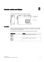
Page 31: ...is equipped with an on off switch The on off switch is used to connect or disconnect the power supply of contact conductors L1 L2 and L3 to the carrier controller The RAIL connection is not switched off The on off switch has 2 positions The 0 and 1 positions are marked on the switch Switch position Meaning Power to the carrier controller is switched off Power to the carrier controller is switched ...

Page 32: ...er as accessory You can use a custom lock instead of the standard version Opening the front panel Turn the key anticlockwise Locking the front panel Turn the key clockwise The front panel has an opening angle of 180 in down direction Display unit The display unit is the receiver of signals from the IR remote control and also has the following functions Display of the current operating mode Display...

Page 33: ... of the modules listed in chapter Replaceable modules Page 40 has failed You must submit the carrier controller to Siemens for repairs if a module that is not listed in the named chapter has failed You can turn in the respective device for repairs to the Retouren Center Fürth The address is Siemens AG Sektor Industry Retouren Center Siemensstr 2 90766 Fürth Germany The identified repair terms appl...

Page 34: ...pen EMS400S carrier controller 6 2 2 Functionality of the EMS400S carrier controller Before you start any repairs check the quality of the signal transmission for communication between PSB C module and PSB S module with the diagnostics unit according to the range of functions offered by the EMS400S diagnostics unit The scope and method of these tests are defined in the operating instructions for t...

Page 35: ...to 48 V AC while the L1 L2 and L3 contact conductors are operated on a voltage of 400 500 V AC Contact with components carrying these live voltages poses the risk of an electrical accident Such an accident can result in physical injury or death Always adhere to the necessary safety measures taken for the respective electrical system components DANGER Electrical accident through fault A mechanical ...

Page 36: ...equirement The EMS carrier is powered off Tool 1 key for the front panel lock Procedure DANGER Electrical accident through contact The RAIL contact conductors are connected to 48 V AC while the L1 L2 and L3 contact conductors are operated on a voltage of 400 500 V AC Contact with components carrying these live voltages poses the risk of an electrical accident Such an accident may lead to injury or...

Page 37: ...ttp support automation siemens com WW view de 36932465 0 en 6 Close and lock the carrier controller If a project is not saved on a memory card in the S7 CPU connect a programming device as described in chapter Connecting a programming device Page 27 and transfer the project Installation 1 Lift the carrier controller onto the four brackets 2 Bolt these brackets to the fastening hooks of the carrier...

Page 38: ...hnology Group Mounted housing Han 3A agg QB 09 20 003 0301 Plug insert Han 3A BU S 09 20 003 2711 Rail connector Harting Technology Group Mounted housing Han Q 8 0 agg metal 09 12 008 0301 Male contact insert Han Q4 2 09 12 006 3041 Han C contact pin c 2 5mm2 09 32 000 6105 Contact pin R 15 STI C 1 5 QMM AWG16 09 15 000 6101 Rubber flange seal 09 12 000 9912 Motor connector Harting Technology Grou...

Page 39: ...that are mounted to the front panel Order number EMC filter 6SE6400 2FA00 6AD0 MICROMASTER 440 frequency converter 6SE6440 2UD15 5AA1 Display unit rear view 6ES7292 0AA50 0AA0 The Siemens modules listed are available on order from the following link Industry Mall http mall automation siemens com The associated documents are available at Overall SIMATIC documentation http www siemens com simatic te...

Page 40: ...efer to the EMS400S PSB Modules operating instructions S7 1212C CPU For information about installation and removal refer to S7 1200 Automation System system manual http support automation siemens com WW view de 36932465 0 en Requirement 1 replacement module Procedure Removal Observe the respective product documentation when removing the spare module Installation 1 Install the module in accordance ...

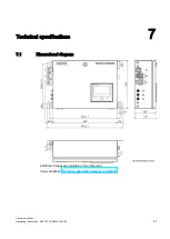
Page 41: ...troller Operating Instructions 09 2013 A5E03474162 02 41 Technical specifications 7 7 1 Dimensional diagram Additional images are available on the Internet at Image database http www automation siemens com bilddb ...

Page 42: ... 0 64 A Inrush current 16 A 0 5 mains periods Power losses typical 40 W Power losses maximum 48 W Geared motor 370 W The system has to protect the energy supply of the carrier controller overcurrent protection with a 3 phase circuit breaker with a rated current of max 63 A Otherwise a 3 phase protection device miniature circuit breaker with a rated current of 63 A and tripping characteristic C can...

Page 43: ...on class EN 61131 2 Protection class I Degree of protection EN 60529 IP65 The information for protection class and degree of protection are only effective once the interfaces of the carrier controller are covered with a matching connector or other suitable means Cable lengths and cable specifications Connection between Cable length Specification Carrier controller EMS rail L1 L2 L3 PE 2 m 2 5 mm r...

Page 44: ...es for the carrier controller are installed using connectors and sockets of Harting Technology Group See chapter Accessories Page 10 7 3 2 Interface X1 Interface for connecting the cables of the geared motor Harting Han Q8 0 socket Contact Allocation 1 Phase U 2 n c 3 Phase W 4 Motor holding brake 5 Motor temperature monitoring 6 Motor holding brake 7 Phase V 8 Motor temperature monitoring 9 PE ...

Page 45: ...ns 09 2013 A5E03474162 02 45 7 3 3 Interface X2 Interface for connecting the power supply cables L1 L2 L3 and PE as well as the cables for communication via RAIL Harting Han Q4 2 socket Contact Allocation 1 400 V contact L1 2 400 V contact L2 3 400 V contact L3 4 n c 5 PE 11 RAIL A 12 RAIL B ...

Page 46: ...ting the braking resistor This connection is optional and depends on whether or not you need a braking resistor Harting Han 3A socket Contact Allocation 1 DC link frequency converter 2 DC link frequency converter 3 n c 4 PE 7 3 5 Interface PN Interface for connecting the cable of a programming device RJ45 socket Contact Allocation 1 Tx 2 Tx 3 Rx 4 5 6 Rx 7 8 ...

Page 47: ...und connector A coded Contact Allocation 1 L 24 V DC 2 Digital signal input DI 1 or DI 3 3 M 0 V DC 4 Digital signal input DI 2 or DI 4 5 Protective earth 7 3 7 Interface X6 An analog digital or combination sensor cable is connected to the interface M12 round connector A coded Contact Assignment 1 L 24 V DC 2 Digital signal input DI 5 3 M 0 V DC 4 Digital signal input DI 6 5 Analog signal input AI...

Page 48: ...blished in the Official Journals of the European Union 2004 108 EC Electromagnetic Compatibility EMC Directive Low Voltage Directive Directive 2006 95 EC of the European Parliament and Council of 12 December 2006 on the harmonization of the laws of the Member States relating to electrical equipment designed for use within certain voltage limits Notes on CE marking Implement appropriate measures fo...

Page 49: ...tuations in which the temperatures of 70 C at the cable entry or 80 C at the branching point of the power and data cables is exceeded at the rated operating conditions Take precautions to prevent the rated voltage from being exceeded by more than 40 as a result of short term malfunctions EC Declaration of Conformity The EC Declarations of Conformity are made available to the responsible authoritie...

Page 50: ... limit class A to EN 55011 in terms of the emission of RF interference and is therefore not approved for operation in residential areas 7 7 Electromagnetic compatibility The device also meets requirements of the EMC legislation on internal European market The EMC test of the device was passed in accordance with the following standards Standard Title Release EN 61000 6 2 2005 EMC Basic technical st...

Page 51: ...000 4 4 A1 Power cable 2 kV Signal cable 1 kV Motor cable 1 kV 3 Surge pulse strength to EN 61000 4 5 Power cable 2 kV Signal cable 2 kV Motor cable 2 kV Sinusoidal disturbance The following table shows the EMC of the device in terms of sinusoidal disturbance Sinusoidal disturbance Value Corresponds to degree of severity RF radiation electromagnetic fields to IEC 61000 4 3 80 amplitude modulation ...

Page 52: ... environmental conditions of this device exceed requirements in accordance with IEC 61131 2 2007 The following specifications apply to devices that are shipped and stored in the original packaging The following values are derived for the significant environmental conditions from the standards stated The following specifications apply to the device transported and stored in the original package Env...

Page 53: ...ection 3 Stationary operation weatherproof Class 3K3 applies 01 12 1994 The following values are derived for the significant environmental conditions from the standards stated Environmental condition Value Comment Temperature 0 to 45 C Applies to installation according to chapter Mounting location and free space for the carrier control Page 17 Atmospheric pressure 1140 to 795 hPa Corresponds to an...

Page 54: ...anical environmental conditions Test Physical variable Value Vibrations IEC 60068 2 6 2007 Test Fc Vibration 1 octave min 10 cycles per axis Frequency range 5 to 8 4 Hz Deflection 3 5 mm 8 4 to 150 Hz vibration acceleration 9 8 m s2 Shock IEC 60068 2 27 2008 Test Ea Shock form Half wave sine Acceleration 15 g Duration 11 ms Number of shocks 3 per axis and direction Tests related to climatic enviro...

Page 55: ...siemens com automation support request Service http support automation siemens com WW view en 16604318 Contacts and office locations http www automation siemens com mcms aspa db en Pages default aspx Training center http sitrain automation siemens com sitrainworld AppLang en SIMATIC product information is available at Industry Portal http www automation siemens com _en portal index htm Overall SIM...

Page 56: ...00S Electric Monorail System 400 Signal EMC Electromagnetic compatibility EN European standard ESD Electrostatic Sensitive Device Co Company GND Ground HF High Frequency IEC International Electronic Commission IP Ingress Protection IR Infrared IT Information Technology LED Light Emitting Diode PC Personal Computer PE Protection Earth PSB C module Power Signal Booster carrier module PSB S module Po...

Page 57: ...ion of data packets from a source station to all other nodes on the data network Transmission to an EMS with the carrier controller means the broadcast of dispatch data from one plant segment controller to all EMS carriers of a plant segment C data Data that is sent the interface from the PSB C module over the RAIL interface Carrier controller The control component of the EMS400S carrier controlle...

Page 58: ...electric monorail system for internal transport e g a conveyor system EMS carrier Mobile component of the EMS and carrier of the carrier controller EMS rail Component of the carrying structure of the EMS As carrier rail it serves to suspend and move the EMS carriers The contact conductors installed on the EMS rail provide the means for the power supply and communication The contact conductors are ...

Page 59: ... Bridge bit Bridge bits 01 are derived from parity 0 and bridge bits 10 are derived from parity 1 PELV Protective extra low voltage in accordance with the PELV standard for the protection against electrical shock PELV is used whenever it is necessary for operational reasons to ground active conductor rails of the extra low voltage or equipment bodies Presence bit The presence bit is mapped to the ...

Page 60: ...e plant segment controller the corresponding communication link is free of error in this case However no user data is transmitted Synchronization signal The synchronization signal serves to ensure synchronous data transmission from all plant segment controllers to the EMS carriers The synchronization signal is generated by a plant segment controller and transmitted simultaneously to all plant segm...

Page 61: ...ntroller 18 E EC Declaration of Conformity 49 EMC test 50 Environmental condition 52 53 Test 54 I Industry Operation 50 Industry Portal 55 Installation EMC compatible 50 Intended 15 Installation as intended 15 Insulation strength 43 Interference Cable bound 52 Radiated 52 M Main dimensions Carrier controller 41 Maintenance 33 O Office location 55 Operation Industry 50 Order unit 10 P Protection cl...

Page 62: ...r 62 Operating Instructions 09 2013 A5E03474162 02 T Technical specifications Electrical system 42 Technical support 55 Technical Support 55 Test Climatic 54 Mechanical 54 Training center 55 Transport damage 17 W Warranty 16 ...

Reviews: