Summary of Contents for 6GK5204-0BA00-2KB2

Page 1: ...tices 2 Security recommendations 3 Network topologies and redundancy 4 Device description 5 Installation and disassembly 6 Connecting up 7 Maintenance and cleaning 8 Functional description and configuration using Web Based Management 9 Technical specifications 10 Accessories and compatible devices 11 Dimension drawings 12 Approvals 13 ...

Page 2: ...re those who based on their training and experience are capable of identifying risks and avoiding potential hazards when working with these products systems Proper use of Siemens products Note the following WARNING Siemens products may only be used for the applications described in the catalog and in the relevant technical documentation If products and components from other manufacturers are used ...

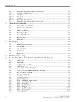
Page 3: ...E X204RNA interfaces 37 5 4 1 TP interfaces 37 5 5 SCALANCE X204RNA EEC product properties 39 5 5 1 SCALANCE X204RNA EEC PRP 39 5 5 2 SCALANCE X204RNA EEC PRP HSR 39 5 5 3 SCALANCE X204RNA EEC HSR 41 5 6 SCALANCE X204RNA EEC interfaces 42 5 6 1 TP interfaces 42 5 6 2 SFP interface 44 5 6 3 SFP interface for application on rail vehicles 45 5 6 3 1 Overview 45 5 6 3 2 SFP991 1 C 45 5 6 3 3 SFP991 1L...

Page 4: ...r 78 7 5 Grounding 79 8 Maintenance and cleaning 81 9 Functional description and configuration using Web Based Management 83 9 1 Introduction 83 9 2 Prerequisite 84 9 3 Assignment of an IP address 86 9 3 1 Introduction 86 9 3 2 Initial assignment of an IP address 87 9 4 Initializing the SCALANCE X204RNA EEC PRP HSR 88 9 5 LED simulation of the WBM 90 9 6 Working with the WBM 92 9 7 The System menu...

Page 5: ...ction 135 9 10 2 Switch Config 135 9 10 3 Port status 136 9 10 4 Switch Forwarding Database 137 9 10 5 LLDP Configuration 139 9 10 6 The Statistics Menu 139 9 10 6 1 Packet Size Statistic 140 9 10 6 2 Packet Type Statistic 141 9 10 6 3 Packet Error Statistic 144 9 10 6 4 PRP Statistic 146 9 10 6 5 Redundancy Statistic 147 10 Technical specifications 149 11 Accessories and compatible devices 153 11...

Page 6: ...Table of contents SCALANCE X 200RNA 6 Operating Instructions 04 2022 C79000 G8976 C342 07 ...

Page 7: ...the SCALANCE X 200RNA product line listed under Validity of the Operating Instructions in this document unless the description relates to a specific device of the product line Product name Covers the following devices SCALANCE X 200RNA SCALANCE X204RNA PRP SCALANCE X204RNA HSR SCALANCE X204RNA EEC PRP SCALANCE X204RNA EEC HSR SCALANCE X204RNA EEC PRP HSR SCALANCE X 200RNA PRP SCALANCE X204RNA PRP ...

Page 8: ...rve the Operating Instructions of the plug in transceivers in addition You can find the supplementary documentation on the Internet pages of Siemens Industry Online Support https support industry siemens com cs ww en ps 15247 Further documentation In the system manuals Industrial Ethernet PROFINET Industrial Ethernet and Industrial Ethernet PROFINET passive network components you will find informa...

Page 9: ...IC NET glossary Explanations of many of the specialist terms used in this documentation can be found in the SIMATIC NET glossary You will find the SIMATIC NET glossary here SIMATIC NET Manual Collection or product DVD The DVD ships with certain SIMATIC NET products On the Internet under the following address 50305045 https support industry siemens com cs ww en view 50305045 Security information In...

Page 10: ...vailable and that the latest product versions are used Use of product versions that are no longer supported and failure to apply the latest updates may increase customer s exposure to cyber threats To stay informed about product updates subscribe to the Siemens Industrial Security RSS Feed under https www siemens com cert https www siemens com cert Note on firmware software support Check regularly...

Page 11: ...ctronic scrap or your Siemens contact Product return https support industry siemens com cs ww en view 109479891 Note the different national regulations License conditions Note Open source software Read the license conditions for open source software carefully before using the product You will find license conditions in the following documents on the supplied data medium DOC_OSS SCALANCE X_74 pdf D...

Page 12: ... person involved must first be electrostatically discharged and grounded Do not bring electronic modules in contact with electrically isolating materials such as plastic film isolating table top pads or clothing made of synthetic fibers Place the modules only on conductive surfaces Pack store and transport electronic modules and components only in conductive packaging such as metalized plastic or ...

Page 13: ...inst explosion WARNING EXPLOSION HAZARD Do not open the device when the supply voltage is turned on Safety instructions for use in hazardous locations according to UL FM HazLoc If you use the device under UL or FM HazLoc conditions you must also adhere to the following safety instructions in addition to the general safety instructions for protection against explosion This equipment is suitable for...

Page 14: ...Safety notices SCALANCE X 200RNA 14 Operating Instructions 04 2022 C79000 G8976 C342 07 ...

Page 15: ... only within a protected network area No product liability will be accepted for operation in a non secure infrastructure Use VPN to encrypt and authenticate communication from and to the devices For data transmission via a non secure network use an encrypted VPN tunnel IPsec OpenVPN Separate connections correctly WBM SSH etc Check the user documentation of other Siemens products that are used toge...

Page 16: ...ity advisories htm Authentication Note Accessibility risk Risk of data loss Do not lose the passwords for the device Access to the device can only be restored by resetting the device to factory settings which completely removes all configuration data Replace the default passwords for all user accounts access modes and applications if applicable before you use the device Define rules for the assign...

Page 17: ...in the device Replace this certificate with a self made certificate with key We recommend that you use a certificate signed either by a reliable external or by an internal certification authority Use a certification authority including key revocation and management to sign certificates Make sure that user defined private keys are protected and inaccessible to unauthorized persons Verify certificat...

Page 18: ...Security recommendations SCALANCE X 200RNA 18 Operating Instructions 04 2022 C79000 G8976 C342 07 ...

Page 19: ...it uses parallel separate networks made up of standard network components The end devices that use this method are connected to the two networks via a preceding device or via two integrated device interfaces This means that the frame of the end device can be transferred at the same time via both networks If a transmission path is interrupted the frame arrives at its destination via the second path...

Page 20: ...the application The second frame received is recognized and discarded This achieves N 1 redundancy without reconfiguration bumpless switchover Note Overlong frames When a SCALANCE X204RNA IE switch feeds a frame with the maximum length into a PRP network the IE switch appends a PRP trailer to the frame Appending the PRP trailer results in an overlong frame that exceeds the maximum permitted frame ...

Page 21: ...ly one Ethernet Interface With all these devices a SCALANCE X 200RNA can be connected upstream from them This allows access for Single Attached Nodes SAN to PRP networks Industrial Ethernet bus linear star or ring structures with switching functionality can be implemented cost effectively with devices of the SCALANCE X product line You will find a list of usable network components in Accessories a...

Page 22: ... two networks via a preceding device or via two integrated device interfaces This means that the frame of the end device can be transferred at the same time in both directions of the ring If a transmission path is interrupted the frame arrives its destination via the other path The devices of the SCALANCE X 200RNA product line are used to connect end devices without integrated HSR interfaces to HS...

Page 23: ...This achieves N 1 redundancy without reconfiguration bumpless switchover There are already end devices equipped with two Ethernet interfaces that are capable of using the High availability Seamless Redundancy Protocol Double Attached Nodes HSR DANH On the other hand there are many end devices starting with S7 controllers right through to control computers that communicate using TCP IP but do not s...

Page 24: ...n standard IEC62439 3 Two SCALANCE X 200RNA devices are required One device is connected with the PRP network LAN A the other with LAN B This means complete communication is still ensured even if one transition point fails SANs connected without RedBox to the decoupled PRP network are an exception from this rule Network topologies and redundancy 4 2 HSR SCALANCE X 200RNA 24 Operating Instructions ...

Page 25: ...X 200RNA device is required The device is connected to the PRP network LAN A and to LAN B Note This type of linking is not recommended because if the transition point fails the communication between HSR and PRP nodes is interrupted Network topologies and redundancy 4 2 HSR SCALANCE X 200RNA Operating Instructions 04 2022 C79000 G8976 C342 07 25 ...

Page 26: ... 6 1 5 0 6 1 5 0 6 1 51 6 1 51 6 1 51 6 1 51 6 1 51 6 1 51 6 1 51 6 1 51 6 0 7 6 6 0 7 6 3 3 Figure 4 4 Topology of a coupling of two HSR rings via a PRP network Network topologies and redundancy 4 3 HSR PRP coupling SCALANCE X 200RNA 26 Operating Instructions 04 2022 C79000 G8976 C342 07 ...

Page 27: ...t P2 B is open and must not be used Setting for device and Redundant HSR PRP coupling LAN B The port P1 A is open and must not be used Configuration of the NetID parameter The network ID of the PRP network is specified with this parameter The valid range of values is 1 to 6 The SCALANCE X204RNA devices between the two rings belong to the same PRP network therefore you need to set the same NetID fo...

Page 28: ... the devices SCALANCE X204RNA to relating to the coupling of the two PRP networks on the WBM page X200 Coupling Configuration You need to configure the following parameters Coupling Mode NetID Configuration of the Coupling Mode parameter Setting for device and Redundant HSR PRP coupling LAN A The port P2 B is open and must not be used Network topologies and redundancy 4 3 HSR PRP coupling SCALANCE...

Page 29: ...P network and you therefore need to set the same value for the NetID parameter for both devices The same applies to the devices SCALANCE X204RNA and The last devices named belong however to a different PRP network and for this reason a different NetID from the devices and must be used For example NetID 5 could be assigned for devices und and NetID 6 for devices and Network topologies and redundanc...

Page 30: ...Network topologies and redundancy 4 3 HSR PRP coupling SCALANCE X 200RNA 30 Operating Instructions 04 2022 C79000 G8976 C342 07 ...

Page 31: ...RNA EEC Properties SCALANCE X204RNA SCALANCE X204RNA EEC SIMATIC environment Operating temperature 40 to 60 C 40 to 70 C up to 85 C max 16h Diagnostics LED 24 V DC 24 250 V DC 100 240 V AC Housing Plastic Metal Coated printed circuit boards as of hardware version 3 2 x 24 V DC 100 Base T full duplex 100 Base T half duplex 10 Base T SFP interface for SFP modules for HSR ports 100 Base FX for HSR po...

Page 32: ...odules SFP991 1 multimode glass up to 3 km 6GK5991 1AD00 8AA0 Fiber single mode duplex LC 2 x SFP modules SFP991 1LD monomode glass up to 26 km 6GK5991 1AF00 8AA0 Fiber single mode duplex LC 2 x SFP modules SFP991 1LH monomode glass up to 70 km 6GK5991 1AE00 8AA0 Standard Ethernet ports PRP ports P1 A P2 B P1 A P2 B HSR ports HSR 1 HSR 2 HSR 1 HSR 2 Note TP connectors of SCALANCE X204RNA EEC The S...

Page 33: ... Ethernet HSR PRP link Unpacking and checking WARNING Do not use any parts that show evidence of damage If you use damaged parts there is no guarantee that the device will function according to the specification If you use damaged parts this can lead to the following problems Injury to persons Loss of the approvals Violation of the EMC regulations Damage to the device and other components Use only...

Page 34: ...pin plug in terminal block signaling contact 3 pin plug in terminal block power supply Safety notices DVD operating instructions SINEC PNI Bracket for guiding the cable mechanical protection Note SFP modules are not supplied with the device Device description 5 2 Product overview SCALANCE X 200RNA 34 Operating Instructions 04 2022 C79000 G8976 C342 07 ...

Page 35: ...ks for connection of end devices or network segments without PRP capability P1 and P2 and two RJ 45 jacks for connecting to PRP networks LAN A and LAN B PRP A and PRP B Figure 5 1 SCALANCE X204RNA PRP Device description 5 3 SCALANCE X204RNA product properties SCALANCE X 200RNA Operating Instructions 04 2022 C79000 G8976 C342 07 35 ...

Page 36: ...network segments without HSR capability P1 A and P2 B and two RJ 45 jacks for connecting to the High availability Seamless Redundancy Protocol ring HSR 1 and HSR 2 Figure 5 2 SCALANCE X204RNA HSR Device description 5 3 SCALANCE X204RNA product properties SCALANCE X 200RNA 36 Operating Instructions 04 2022 C79000 G8976 C342 07 ...

Page 37: ...5 n c Pin 4 n c Pin 3 TD Pin 2 RD Pin 1 RD Note TP cords or TP XP cords with a maximum length of 10 m can be connected to the RJ 45 TP port With the IE FC cables and IE FC RJ 45 plug 180 an overall cable length of up to 100 m is permitted between two devices depending on the cable type Note The interfaces of the SCALANCE X204RNA meet the requirements for environment B according to IEEE 802 3 secti...

Page 38: ...play device that does not require settings to be made for commissioning MDI MDI X autocrossover function The advantage of the MDI MDI X autocrossover function is that straight through cables can be used throughout and crossover Ethernet cables are unnecessary This prevents malfunctions resulting from mismatching send and receive wires This makes installation much easier for the user The SCALANCE X...

Page 39: ... capability are connected to the RJ 45 jacks P1 and P2 Figure 5 4 SCALANCE X204RNA EEC PRP 5 5 2 SCALANCE X204RNA EEC PRP HSR Possible attachments The SCALANCE X204RNA EEC PRP HSR has four RJ 45 jacks and two slots for SFP modules The SFP modules can be used as alternatives to the two RJ 45 jacks A H1 and B H2 and are intended to connect networks LAN A and LAN B or to connect to the High availabil...

Page 40: ...P or HSR capability are connected to the RJ 45 jacks 1 1 B and 2 2 B Figure 5 5 SCALANCE X204RNA EEC PRP HSR Device description 5 5 SCALANCE X204RNA EEC product properties SCALANCE X 200RNA 40 Operating Instructions 04 2022 C79000 G8976 C342 07 ...

Page 41: ...SR 2 and are intended for connection to the High availability Seamless Redundancy Protocol ring Standard Ethernet end devices or network segments that do not support HSR or networks to be linked are connected to the RJ 45 jacks P1 A and P2 B Figure 5 6 SCALANCE X204RNA EEC HSR Device description 5 5 SCALANCE X204RNA EEC product properties SCALANCE X 200RNA Operating Instructions 04 2022 C79000 G89...

Page 42: ...Pin 4 n c Pin 3 TD Pin 2 RD Pin 1 RD Note TP cords or TP XP cords with a maximum length of 10 m can be connected to the RJ 45 TP port With the IE FC cables and IE FC RJ 45 plug 180 an overall cable length of up to 100 m is permitted between two devices depending on the cable type Note The interfaces of the SCALANCE X204RNA EEC PRP and HSR and PRP HSR meet the requirements for environment B accordi...

Page 43: ...RP and HSR is a plug and play device that does not require settings to be made for commissioning MDI MDIX autocrossover function The advantage of the MDI MDIX autocrossover function is that straight through cables can be used throughout and crossover Ethernet cables are unnecessary This prevents malfunctions resulting from mismatching send and receive wires This makes installation much easier for ...

Page 44: ...pplied protective caps Transmission medium and range Note The SFP slots are intended for SFP transceivers with optical interface SFP inserts with electrical interface RJ45 are not supported Table 5 4 SFP transceiver overview SFP transceiver SFP991 1 SFP991 1LD SFP991 1LH Transmission medium Wavelength Core diameter Outer diameter Multimode FO cable 1310 nm 50 or 62 5 µm 125 µm Monomode FO cable 13...

Page 45: ...8FA0 SFP992 1LD C 6GK5 992 1AM00 8FA0 Note The SFP modules do not ship with the product and must be ordered separately if needed 5 6 3 2 SFP991 1 C Properties Transmission mode 100Base FX complying with IEEE 802 3 Transmission rate 100 Mbps Fast Ethernet Transmission medium Multimode fiber optic cable Light source LED Class1 LASER Eye safe Wavelength 1300 nm Cable length max At 50 µm fiber core di...

Page 46: ...put Sensitivity min 28 dBm Input power max 8 dBm Depending on the cable used you can find additional information in the Industrial Ethernet PROFINET Passive network components System Manual see also section Introduction paragraph Additional documentation 5 6 3 4 SFP992 1LD C Properties Transmission mode 1000Base LX complying with IEEE 802 3 Transmission rate 1000 Mbps Gigabit Ethernet Transmission...

Page 47: ... inserted in the replacement device The first time it is started up the replacement device has the same configuration as the failed device except for the MAC address set by the vendor Compatible devices As a general rule the data on the C PLUG is only compatible with devices having an identical order number and the same device name Over and above this the data of the SCALANCE X204RNA and the SCALA...

Page 48: ...the power to the device 2 Remove the protective cover 3 Insert the C PLUG in the intended compartment 4 Close the protective cover Note The C PLUG may only be inserted or removed when the power is off Removing the C PLUG Follow the steps below to remove the C PLUG 1 Turn off the power to the device 2 Remove the protective cover 3 Remove the C PLUG from the compartment using flat pliers tweezers or...

Page 49: ...T SET button Figure 5 8 The five button phases Time the button is pressed in seconds Table 5 5 Button phases Phase Description 1 The currently set fault mask is displayed If no fault mask has been set all ports flash one after the other If you release the SELECT SET button in phase 1 this has no effect 2 The LEDs of the ports at which there is currently a link flash at 2 5 Hz If you release the SE...

Page 50: ...onds the mode LED returns toflashing mode SELECT SET button can be released without setting a mode If you have accidentally programmed the wrong mode e g by releasing at the switchover moment you can trigger a factory reset after the normal startup with the normal SELECT SET button functionality press for 10 seconds and reverse the programming Position of the SELECT SET button and C PLUG Note On t...

Page 51: ... C PLUG SELECT SET button Figure 5 9 Position of the C PLUG and SELECT SET button Device description 5 8 SELECT SET button SCALANCE X 200RNA Operating Instructions 04 2022 C79000 G8976 C342 07 51 ...

Page 52: ...redundant power supplies 3 C PLUG error 4 Device startup the LED is lit for approx 20 seconds 5 Internal error 6 A redundancy error was detected 7 No problem has been detected by the SCALANCE X 200RNA PRP 5 9 1 2 Power LED The LEDs signal the following statuses of the SCALANCE X 200RNA PRP The status of the power supply is indicated by a green LED Device type SCALANCE LED lit green LED lit yellow ...

Page 53: ...seconds 4 Setting or display of the fault mask 5 9 1 4 LED displays during startup When the SCALANCE X 200RNA PRP starts up the following LED displays light up in the order shown 1 Power LEDs green light up immediately after turning on the power 2 Port LEDs go off the red error LED is lit for approx 10 seconds 3 Following startup the correct link status is indicated by the port LEDs after approxim...

Page 54: ...s lit red a SCALANCE X 200RNA HSR has detected an error fault At the same time the signaling contact opens assuming that the response of the signaling contact has not been configured differently The LED signals that the SCALANCE X 200RNA HSR can adopt the following statuses Device type SCALANCE LED lit red LED lit yellow LED not lit X204RNA HSR 1 2 3 4 5 6 7 8 X204RNA EEC HSR 1 3 4 5 6 7 8 X204RNA...

Page 55: ...or LEDs Device type SCALANCE LED lit green LED lit yellow LED flashes yel low Number of LEDs X204RNA HSR 2 port LEDs 1 2 3 4 2 PRP port LEDs 1 2 3 4 X204RNA EEC HSR 2 port LEDs 1 2 3 4 2 PRP port LEDs 1 2 3 4 X204RNA EEC PRP HSR If configured as HSR device 2 port LEDs 1 2 3 4 2 PRP port LEDs 1 2 3 4 1 TP link exists no data reception 2 TP link data received at TP port 3 Device startup the LED is l...

Page 56: ... on its housing in other words that of the SCALANCE X204RNA EEC PRP and the SCALANCE X204RNA EEC HSR Depending on how you configure the SCALANCE X204RNA EEC PRP HSR the labeling is valid as described in the sections above The exception is the mode LED third LED from the top When the LED is lit the SCALANCE X204RNA EEC PRP HSR is in HSR mode This means that the right hand labeling of the LED displa...

Page 57: ...stalled in a cabinet the inner temperature of the cabinet corresponds to the ambient temperature of the device WARNING If the cable or conduit entry point exceeds 70 C or the branching point of conductors exceeds 80 C special precautions must be taken If the equipment is operated in an air ambient in excess of 60 only use cables with admitted maximum operating temperature of at least 80 NOTICE Imp...

Page 58: ...p to the following safety instructions in addition to the general safety instructions for protection against explosion The following information applies only to the SCALANCE X204RNA WARNING To comply with EU Directive 2014 34 EU ATEX 114 UK Regulation SI 2016 1107 or the conditions of IECEx or CCC Ex the housing or cabinet must meet the requirements of at least IP54 according to EN IEC 60529 GB T ...

Page 59: ...ions for the control cabinets or housings are adhered to The control cabinet cover or housing must be secured so that it can only be opened with a tool An appropriate strain relief assembly for the cable must be used Safety notices when using the device according to ATEX IECEx and FM If you use the device under ATEX IECEx or FM conditions you must also observe the following safety notices in addit...

Page 60: ...ed control room Additional notes CAUTION Use only approved components If you use components and accessories that are not approved for SIMATIC NET devices or their target systems this may violate the requirements and regulations for safety and electromagnetic compatibility Only use components approved for the SIMATIC NET devices NOTICE Warming and premature aging of the IE switch due to direct sunl...

Page 61: ...of the housing Minimum clearances If you install the SCALANCE X 200RNA without forced ventilation or cooling minimum clearances must be maintained to neighboring devices or the wall of the housing By keeping to the minimum clearances there is then an adequate stream of air for heat dissipation during operation Keep to the following minimum clearances to neighboring devices Table 6 1 Minimum cleara...

Page 62: ...ANCE X204RNA EEC SCALANCE X204RNA EEC allows the following mounting positions Horizontal Horizontal installation of the rack DIN rail Vertical Vertical installation of the rack DIN rail Remember that the permitted temperature ranges depend on the position of the installed device You will find the permitted temper ature ranges in the section Technical specifications Page 149 Installation and disass...

Page 63: ...e device down against the DIN rail until it locks into place 3 Fit the connectors for the power supply 4 Fit the connectors for the signaling contact 5 Insert the terminal blocks into the sockets on the device Figure 6 1 Mounting on a 35 mm DIN rail based on the example of a SCALANCE X204RNA EEC Installation and disassembly 6 5 Mounting on DIN rails SCALANCE X 200RNA Operating Instructions 04 2022...

Page 64: ...t top Lock in position below Secure with the screw Figure 6 2 Mounting the protective bracket on the SCALANCE X204RNA EEC Installation and disassembly 6 5 Mounting on DIN rails SCALANCE X 200RNA 64 Operating Instructions 04 2022 C79000 G8976 C342 07 ...

Page 65: ...l catch on the bottom of the device using a screwdriver 3 Then pull the lower part of the device away from the DIN rail Figure 6 3 Removing from a 35 mm DIN rail based on the example of the SCALANCE X204RNA Installation and disassembly 6 5 Mounting on DIN rails SCALANCE X 200RNA Operating Instructions 04 2022 C79000 G8976 C342 07 65 ...

Page 66: ...the electrical cable connecting cables 3 Fit the connectors for the signaling contact 4 Insert the terminal blocks into the sockets on the SCALANCE X204RNA 5 Screw the device to the wall Note The wall mounting must be capable of supporting at least four times the weight of the SCALANCE X204RNA see Technical specifications Page 149 Wall mounting of a SCALANCE X204RNA EEC To mount the device on a wa...

Page 67: ... DIN rail 35 mm to the wall 2 Now mount the SCALANCE X 204RNA on the DIN rail as described in the section DIN rail mounting See also Mounting on DIN rails Page 63 Dimension drawings Page 159 Installation and disassembly 6 6 Wall mounting SCALANCE X 200RNA Operating Instructions 04 2022 C79000 G8976 C342 07 67 ...

Page 68: ...sembly observe the following Before starting work ensure that the electricity is switched off Secure remaining connections so that no damage can occur as a result of disassembly if the system is accidentally started up Installation and disassembly 6 7 Disassembly SCALANCE X 200RNA 68 Operating Instructions 04 2022 C79000 G8976 C342 07 ...

Page 69: ...power supply unit for the device must meet NEC Class 2 according to the National Electrical Code r ANSI NFPA 70 If the equipment is connected to a redundant power supply two separate power supplies both must meet these requirements WARNING Maximum current The maximum current via the terminals is 10 A You should therefore include a fuse that trips at a current higher than 10 A The fuse must meet th...

Page 70: ...of protection required by EN IEC IEC 60079 0 GB 3836 1 WARNING Unsuitable cables or connectors Risk of explosion in hazardous areas Only use connectors that meet the requirements of the relevant type of protection If necessary tighten the connector screw connections device fastening screws grounding screws etc according to the specified torques Close unused cable openings for electrical connection...

Page 71: ...e the device approvals applicable for your country Notes for use in hazardous locations according to ATEX IECEx UKEX and CCC Ex If you use the device under ATEX IECEx UKEX or CCC Ex conditions you must also keep to the following safety instructions in addition to the general safety instructions for protection against explosion The following information applies only to the SCALANCE X204RNA WARNING ...

Page 72: ... LAN segment with all the interconnected devices should be contained completely in a single low voltage power distribution in a building The LAN is designed either for Environment A according to IEEE802 3 or Environment 0 according to IEC TR 62102 Do not connect any electrical connectors directly to the telephone network telephone network voltage or a WAN Wide Area Network Connecting up 7 1 Safety...

Page 73: ...ontact are coded differently from the connection of the power supply The plugs for power supply and signaling contact cannot therefore be interchanged You can use non coded plugs in coded sockets and coded plugs in non coded sockets Pin assignment Pin number Pin assignment of the SCALANCE X204RNA PRP and HSR Pin assignment of the SCALANCE X204RNA EEC PRP and HSR and PRP HSR Pin 1 L1 24 VDC PE Codi...

Page 74: ...ng contact can be subjected to a maximum load of 100 mA safety extra low voltage SELV 24 VDC Never operate the SCALANCE X204RNA PRP and HSR with AC voltage or DC voltage higher than 28 8 V DC 24 VDC power supply NOTICE If the SCALANCE X204RNA is supplied over long 24 V power supply lines or networks measures are necessary to prevent interference by strong electromagnetic pulses on the supply lines...

Page 75: ...ith a 100 to 240 VAC or 24 to 250 VDC power supply are not approved for use in hazardous areas according to EC RL 94 9 ATEX NOTICE Securing cables with dangerous voltage Make sure that the connector cannot be released accidentally by pulling on the connecting cable Lay the cables in cable ducts or cable channels and secure the cables where necessary with cable ties Protective ground WARNING PE con...

Page 76: ...nt of the SCALANCE X 204RNA Pin assignment of the SCALANCE X 204RNA EEC Pin 1 F1 NO contact NC contact if a fault occurs F1 NC contact NO contact if a fault occurs Coding of the plug Pin 2 F2 F2 Pole terminal Coding of the socket Pin 3 F3 NO contact NC contact if a fault occurs Coding of the plug The following errors faults can be signaled by the signaling contact The failure of a link at a monito...

Page 77: ...rrelates with the red fault LED Exception The absence of the power supply is signaled only by the signaling contact no display by the fault LEDs Note During startup the signaling contract is always active signals error fault Connecting up 7 3 Signaling contact SCALANCE X 200RNA Operating Instructions 04 2022 C79000 G8976 C342 07 77 ...

Page 78: ...FP transceiver The SFP modules are supplied with power via the SFP slot of the SCALANCE X204RNA EEC Connecting up 7 4 SFP transceiver SCALANCE X 200RNA 78 Operating Instructions 04 2022 C79000 G8976 C342 07 ...

Page 79: ...il There is also a grounding bolt on the underside of the housing Connect the grounding bolt of the device to the nearest grounding point using the grounding cable To do this use the same wire cross section as the power supply cable however not smaller than 1 5 mm 16 AWG Connecting up 7 5 Grounding SCALANCE X 200RNA Operating Instructions 04 2022 C79000 G8976 C342 07 79 ...

Page 80: ...Connecting up 7 5 Grounding SCALANCE X 200RNA 80 Operating Instructions 04 2022 C79000 G8976 C342 07 ...

Page 81: ... manuals for the device or supplied with the accessories or spare parts CAUTION Hot surfaces Risk of burns during maintenance work on parts with a surface temperature above 70 C 158 F Take appropriate protective measures for example wear protective gloves Once maintenance work is complete restore the touch protection measures NOTICE Cleaning the housing If the device is not in a hazardous area onl...

Page 82: ...Maintenance and cleaning SCALANCE X 200RNA 82 Operating Instructions 04 2022 C79000 G8976 C342 07 ...

Page 83: ...ction to the device is necessary Note To prevent unauthorized access to the SCALANCE X200RNA there is an automatic logout after 15 minutes or after the time configured in the Agent Timeout Configuration menu A manual logout is also possible with the appropriate button in the user interface Exiting the browser does not close the session If the browser is started again within the timeout the session...

Page 84: ...Web Based Management see section Assignment of an IP address Page 86 To use Web Based Management there must be an Ethernet connection between the SCALANCE X 200RNA and the client computer Use of a Microsoft Internet Explorer version 8 or higher is recommended All the pages of Web Based Management require JavaScript You should therefore make sure that Java Script is enabled in your browser settings...

Page 85: ...ad access to the configuration data of the SCALANCE X 200RNA 3 Enter your password in the Password input box If you have not yet set a password the default passwords as shipped apply Enter admin if you selected admin as the user name or user if you selected user Note For security reasons make sure that you change the original factory set passwords 4 Click the Log On button to start the logon Note ...

Page 86: ...C 1518 and RFC 1519 An IP address consists of 4 bytes Each byte is represented in decimal with a dot separating it from the previous one This results in the following structure where XXX stands for a number between 0 and 255 XXX XXX XXX XXX The IP address is made up of two parts the network ID and the host ID This allows different subnets to be created Depending on the bytes of the IP address used...

Page 87: ...t be no zeros between the ones 9 3 2 Initial assignment of an IP address Configuration options An initial IP address for an IE switch cannot be assigned using Web Based Management or the Command Line Interface because these configuration tools require that an IP address already exists The following options are available to assign an IP address to an unconfigured device currently without an IP addr...

Page 88: ...art buttons The device is then restarted and is in the selected operating mode Figure 9 2 Initializing the SCALANCE X204RNA EEC PRP HSR using WBM Initializing with CLI You can also initialize the SCALANCE X204RNA EEC PRP HSR using the CLI command setmode PRP HSR Go to top of menu tree Go up in menu tree Show menus commands exit Exit from CLI TELNET session restart Shutdown and startup again setmod...

Page 89: ...ter you have initialized the SCALANCE X204RNA PRP HSR and restarted the device the corresponding dialog box is displayed in WBM Figure 9 3 SCALANCE X204RNA EEC PRP HSR in PRP mode Figure 9 4 SCALANCE X204RNA EEC PRP HSR in HSR mode Functional description and configuration using Web Based Management 9 4 Initializing the SCALANCE X204RNA EEC PRP HSR SCALANCE X 200RNA Operating Instructions 04 2022 C...

Page 90: ...herefore displays simulated LEDs The top quarter of the screen shows a schematic representation of the SCALANCE X 200RNA with the corresponding LEDs The meaning of the LED displays is described in the section LEDs Page 52 in these Operating Instructions Figure 9 5 LED simulation of the SCALANCE X204RNA EEC Functional description and configuration using Web Based Management 9 5 LED simulation of th...

Page 91: ...6 LED simulation of the SCALANCE X204RNA Functional description and configuration using Web Based Management 9 5 LED simulation of the WBM SCALANCE X 200RNA Operating Instructions 04 2022 C79000 G8976 C342 07 91 ...

Page 92: ...link you log out from the device Updating the display with Refresh Web Based Management pages have a Refresh button at the lower edge of the page Click this button to request up to date information from the IE switch for the current page Storing entries with Set Values Pages in which you can make configuration settings have a Set Values button at the lower edge Click this button to save the config...

Page 93: ...1 time frame or SNTP You can also see when and how it was set m The setting was made manually p The setting was made by the Simple Network Time Protocol SNTP System Up Time read only The time since the last restart Device Type read only The type designation of the device Device Description read only The type description of the device Functional description and configuration using Web Based Managem...

Page 94: ... Identification Maintenance The following dialog box contains information on device specific vendor and maintenance data such as the order number serial number version numbers Figure 9 8 System Identification Maintenance I M 0 Here you can see the individual parameters for Identification Maintenance Functional description and configuration using Web Based Management 9 7 The System menu SCALANCE X ...

Page 95: ...rting the SCALANCE X 200RNA as well as an option for resetting the settings of the SCALANCE X 200RNA Figure 9 9 System Restart and Defaults Functional description and configuration using Web Based Management 9 7 The System menu SCALANCE X 200RNA Operating Instructions 04 2022 C79000 G8976 C342 07 95 ...

Page 96: ...tialized the internal firmware is reloaded and the device runs a self test The learned entries in the address table are deleted You can leave the browser window open while the SCALANCE X 200RNA restarts Restore Factory Defaults and Restart Click the Restore Factory Defaults and Restart button to restore the factory default configuration settings The protected defaults are also reset An automatic r...

Page 97: ...e and directory path of the file from which you want to load the new FPGA configuration SSL Private Key File Name and directory path of the file from which you want to load the new SSL key SSL Certificate File Name and directory path of the file from which you want to load the new SSL certificate Functional description and configuration using Web Based Management 9 7 The System menu SCALANCE X 200...

Page 98: ...r firmware and a newer FPGA version required on the device it is advisable to download the FPGA and then the firmware following the restart How to save data using HTTP 1 Start the save function by clicking either the Save Configuration or Save Private MIB button 2 You will be prompted to select a storage location and a name for the file or to accept the proposed file name Reusing configuration dat...

Page 99: ...t version is stored permanently on the SCALANCE X 200RNA FPGA Version The FPGA version is shown here Firmware The version of the firmware running on the SCALANCE X 200RNA FW Build The date on which the firmware running on the SCALANCE X 200RNA was created is displayed here Order Number The order number of the device is shown here Functional description and configuration using Web Based Management ...

Page 100: ...ator you can change the passwords for Admin and User The password can be up to a maximum of 16 characters 7 bit ASCII long Figure 9 12 System Passwords You apply your settings with Set Values Functional description and configuration using Web Based Management 9 7 The System menu SCALANCE X 200RNA 100 Operating Instructions 04 2022 C79000 G8976 C342 07 ...

Page 101: ...s available with the button in the section SELECT SET button Page 49 On this page the functionality of the SELECT SET button can be restricted or fully disabled This is possible for the following three functionalities Restore Factory Defaults Enable Disable Reset Set Fault Mask Figure 9 13 Select Set button configuration Functional description and configuration using Web Based Management 9 7 The S...

Page 102: ...nts and to display them on the page of the Log Table menu This for example allows you to record when an SNMP authentication attempt failed or when the connection status of a port has changed You can specify which events are logged in the Agent Event Configuration menu item Figure 9 14 System Event Log Table Functional description and configuration using Web Based Management 9 7 The System menu SCA...

Page 103: ... A SCALANCE X 200RNA allows configuration data to be stored on an external C PLUG and configuration data to be loaded from an external C PLUG The C PLUG information menu allows you to read out the inserted C PLUG and to manage configuration data stored on it Figure 9 15 C PLUG Information Functional description and configuration using Web Based Management 9 7 The System menu SCALANCE X 200RNA Oper...

Page 104: ...LUG File System Usage readonly Size of the memory of the C PLUG used by the data system C PLUG Info String read only Information line of the C PLUG Modify C PLUG Modification of the configuration stored on the C PLUG Copying the current configuration on the C PLUG with associated restart Copying the factory configuration to the C PLUG with associated restart Deleting the configuration stored on th...

Page 105: ...s if you click the X200 folder icon The dialog box shows information about the power supply and the error status Figure 9 16 X200 Status Functional description and configuration using Web Based Management 9 8 The X200 menu SCALANCE X 200RNA Operating Instructions 04 2022 C79000 G8976 C342 07 105 ...

Page 106: ...examples of possible error messages If more than one problem has occurred they are listed in the text box one above the other Error messages Meaning Redundant power line down The redundant power supply has failed Link down on monitored port The connection to a monitored port is interrupted No Fault The SCALANCE X 200RNA has not detected a fault the signaling contact has not responded and the fault...

Page 107: ... The mode used is PRP previously PRP Mode 1 This value cannot be changed Duplicate Aging Time The default value from the PRP standard is 400 ms This value cannot be changed Functional description and configuration using Web Based Management 9 8 The X200 menu SCALANCE X 200RNA Operating Instructions 04 2022 C79000 G8976 C342 07 107 ...

Page 108: ...ce numbers that can be filtered per Source MAC address also increases At the same time the number of Source MAC addresses whose packets can be filtered decreases When you decrease the number of possible Source MAC addresses fewer sequence numbers can be filtered per Source MAC address However the number of Source MAC addresses that the duplicate filter can filter is increased Note Increasing the S...

Page 109: ... HSR PRP coupling P1 A is connec ted with LAN A of a PRP network P2 B is open and may not be used Redundant HSR PRP coupling LAN B Setting with redundant HSR PRP coupling P1 B is connec ted with LAN B of a PRP network P1 A is open and may not be used NetID Here you can set the network ID of the connected PRP network The valid value range is 1 to 6 The NetID is used to distinguish between frames fr...

Page 110: ...ardless of Ethertypes and any VLAN priorities 9 8 4 Supervision Frames In the Supervision Frames dialog box you enable disable sending of Supervision Frames per port Figure 9 19 Supervision Frames Send Supervision Frames on Port Select the check box for the ports at which you want to send Supervision Frames When the check box for a port is cleared neither are own Supervision Frames sent to this po...

Page 111: ...epending on the configuration of the event table can trigger a trap or an entry in the log table Device related link monitoring of the ports A SCALANCE X 200RNA provides device related link monitoring A link up or link down also affects the message system if the SCALANCE X 200RNA was appropriately configured Setting of the X200 Fault Mask Power dialog box on the device Optionally the dialog box ca...

Page 112: ...e two power supplies of the SCALANCE X204RNA line 1 and line 2 is monitored A fault is then indicated by the message system when there is no power on one of the monitored lines line 1 or line 2 or when the voltage is too low less than 14 V Note This dialog box is not displayed with the SCALANCE X204RNA EEC because it does not have a redundant power supply Functional description and configuration u...

Page 113: ...his port because for example the cable is not plugged in or the connected device is turned off An error fault can be signaled in the following ways depending on the configuration of the SCALANCE X 200RNA Signaling contact fault LED SNMP trap entry in the log table and the syslog Functional description and configuration using Web Based Management 9 8 The X200 menu SCALANCE X 200RNA Operating Instru...

Page 114: ...lid link at this port because for example the cable should not be plugged in An error fault can be signaled in the following ways depending on the configuration of the SCALANCE X 200RNA Signaling contact fault LED SNMP trap entry in the log table and the syslog Functional description and configuration using Web Based Management 9 8 The X200 menu SCALANCE X 200RNA 114 Operating Instructions 04 2022...

Page 115: ...x provides you with options for the IP address You can specify whether a SCALANCE X 200RNA obtains the IP address dynamically or you can assign a fixed address Figure 9 23 Agent Configuration Functional description and configuration using Web Based Management 9 9 The Agent menu SCALANCE X 200RNA Operating Instructions 04 2022 C79000 G8976 C342 07 115 ...

Page 116: ...otocol BOOTP Here you specify whether the IP address can be obtained using the Bootstrap Protocol DCP If you select this option the device can be accessed and configured using DCP SINEC PNI and STEP 7 DCP Read Only If you select this option the configuration data can only be read via DCP SINEC PNI and STEP 7 Agent IP Configuration IP Address Enter the IP address of the SCALANCE X 200RNA here Subne...

Page 117: ...is dialog box you can send a PING to another device in the network to check whether it can be reached Figure 9 24 Ping IP Address Enter the IP address of the target device here Repeat Here enter how often the ping should be sent Ping If you click the Ping button you start the ping Functional description and configuration using Web Based Management 9 9 The Agent menu SCALANCE X 200RNA Operating Ins...

Page 118: ...mmunity string A community string contains information about the user name and password in a string Different community strings are defined for read and write permissions More complex and more secure authentications are possible only in some SNMPv2 variants and in SNMPv3 Note To preserve security you should not use the default values public or private Configuration of SNMP with a SCALANCE X 200RNA...

Page 119: ...ith SNMPv1 v2c Read Community String Here you enter the read community string maximum of 63 characters for the SNMP protocol Read Write Community String Here you enter the write community string maximum of 63 characters for the SNMP protocol Traps This enables disables the sending of SNMPv1 v2c traps Functional description and configuration using Web Based Management 9 9 The Agent menu SCALANCE X ...

Page 120: ...ation Page 126 Note Traps are sent only when the Traps option was selected in SNMP Configuration Figure 9 26 SNMPv1 Trap Configuration IP Address Here you enter the IP addresses of the stations to which a SCALANCE X 200RNA will send traps Enable Trap Click on the check box next to the IP addresses to enable the sending of traps to the corresponding stations Functional description and configuration...

Page 121: ...ss rights of these groups can also be found in the table Figure 9 27 SNMPv3 Groups By clicking the New Entry button or clicking on an entry the SNMPv3 Group Configuration dialog box is displayed Functional description and configuration using Web Based Management 9 9 The Agent menu SCALANCE X 200RNA Operating Instructions 04 2022 C79000 G8976 C342 07 121 ...

Page 122: ...up according to the parameters set above Current Entries By clicking the Current Entries button you exit the SNMPv3 Group Configuration dialog box and return to the SNMPv3 Groups dialog box 9 9 6 SNMP v3 User SNMP v3 User The SNMPv3 Users dialog box appears if you click the Users folder icon Functional description and configuration using Web Based Management 9 9 The Agent menu SCALANCE X 200RNA 12...

Page 123: ...he user in the table Figure 9 29 SNMPv3 Users By clicking the New Entry button or clicking on an entry the SNMPv3 Users Configuration dialog box is displayed Functional description and configuration using Web Based Management 9 9 The Agent menu SCALANCE X 200RNA Operating Instructions 04 2022 C79000 G8976 C342 07 123 ...

Page 124: ...es button you create a user according to the parameters set above Current Entries By clicking the Current Entries button you exit the SNMPv3 Users Configuration dialog box and return to the SNMPv3 Users dialog box Functional description and configuration using Web Based Management 9 9 The Agent menu SCALANCE X 200RNA 124 Operating Instructions 04 2022 C79000 G8976 C342 07 ...

Page 125: ... Here you specify the WBM timeout Permitted values for the WBM timeout 0 3600 seconds 0 means There is no automatic logout CLI TELNET SSH Serial sec Here you specify the CLI timeout Permitted values for the CLI timeout 60 600 seconds Functional description and configuration using Web Based Management 9 9 The Agent menu SCALANCE X 200RNA Operating Instructions 04 2022 C79000 G8976 C342 07 125 ...

Page 126: ...oxes you specify which events trigger which reactions on the SCALANCE X 200RNA The following options are available The SCALANCE X 200RNA sends an e mail with the error message The SCALANCE X 200RNA triggers an SNMP trap Functional description and configuration using Web Based Management 9 9 The Agent menu SCALANCE X 200RNA 126 Operating Instructions 04 2022 C79000 G8976 C342 07 ...

Page 127: ...200RNA writes an entry to the Syslog server Figure 9 32 Agent Event Configuration with the SCALANCE X204RNA EEC Functional description and configuration using Web Based Management 9 9 The Agent menu SCALANCE X 200RNA Operating Instructions 04 2022 C79000 G8976 C342 07 127 ...

Page 128: ...ng handled again via a port that had previously failed Authentication Failure There was an SNMP access with a bad password or inadequate access rights Power Error SCALANCE X204RNA only This event occurs only when power supply line 1 and line 2 are monitored It indicates that there was a change to line 1 or line 2 Functional description and configuration using Web Based Management 9 9 The Agent men...

Page 129: ...rror is reset if the difference in PRP frames received in LAN A and B remains almost the same If a PRP B frame is received at PRP A or vice versa the error is set until no more incorrect frames are received for approximately 30 seconds 9 9 9 Agent E Mail Configuration Setting the e mail client Here you can set the recipient sender and the SMTP server Figure 9 34 Agent E Mail Configuration Function...

Page 130: ... server From Field Here enter the e mail address of the sender 9 9 10 Agent Syslog Configuration Setting the Syslog server Here you can specify the address of the Syslog server Figure 9 35 Agent Syslog Configuration Functional description and configuration using Web Based Management 9 9 The Agent menu SCALANCE X 200RNA 130 Operating Instructions 04 2022 C79000 G8976 C342 07 ...

Page 131: ...figuration Setting the DHCP mode There are several ways of identifying the SCALANCE X 200RNA in the configuration of the DHCP server with the MAC address with a freely defined client ID Functional description and configuration using Web Based Management 9 9 The Agent menu SCALANCE X 200RNA Operating Instructions 04 2022 C79000 G8976 C342 07 131 ...

Page 132: ...selected and the text disabled is displayed DHCP Client ID For the DHCP mode via Client ID you can assign an identification string here that is assigned to a SCALANCE X 200RNA and will be evaluated by the DHCP server Functional description and configuration using Web Based Management 9 9 The Agent menu SCALANCE X 200RNA 132 Operating Instructions 04 2022 C79000 G8976 C342 07 ...

Page 133: ...If no time of day synchronization was possible the box displays Date time not set You can also set the date and time manually the required input format is MM DD YYYY HH MM SS In this case the text box displays the data and time along with the suffix m If the system time was set as a result of synchronization with a server the suffix is p Time Synchronization This box is read only and shows when th...

Page 134: ...ways sends UTC time This time is then recalculated and displayed as the local time based on the time zone There is no standard daylight saving time switchover on the SCALANCE X 200RNA Init Poll Interval Here you can enter the interval at which a SCALANCE X 200RNA repeats the poll when the system time is initially set if this was not successful the first time Poll Interval Once the system time has ...

Page 135: ... aging Display of statistical data 9 10 2 Switch Config Switch functionality The Switch Configuration dialog box appears if you click the Switch folder icon In this dialog box you specify the aging time of the SCALANCE X 200RNA Figure 9 38 Switch Configuration Functional description and configuration using Web Based Management 9 10 The Switch menu SCALANCE X 200RNA Operating Instructions 04 2022 C...

Page 136: ...different switch port If the check box is not enabled a SCALANCE X 200RNA does not delete learnt addresses automatically Aging Time sec Here you enter the time after which the SCALANCE X 200RNA deletes an address if it has not received frames with the corresponding sender address Here the aging time can be set as required within the range from 1 to 655 seconds 9 10 3 Port status Overview of the co...

Page 137: ...an enabled port Note With the SCALANCE X 200RNA the ports cannot be turned off Link Shows the connection status to the network The available options are as follows Up The port has a valid link to the network a link integrity signal is being received Down The link is down for example because the connected device is turned off 9 10 4 Switch Forwarding Database The Switch Forwarding Database dialog b...

Page 138: ...with the learnt destination MAC address must be output Duplicate Filter Shows whether the MAC address is listed as a source MAC address in the duplicate filter table Proxy Node Shows whether the MAC address is listed as a source MAC address in the proxy node table Functional description and configuration using Web Based Management 9 10 The Switch menu SCALANCE X 200RNA 138 Operating Instructions 0...

Page 139: ...9 10 6 The Statistics Menu Counting and evaluation of received frames A SCALANCE X 204RNA has internal statistics counters with which it counts the number of received frames for each port according to the following criteria Frame length Message frame type Bad frames This information provides you with an overview of the data traffic and any problems on the network Functional description and configu...

Page 140: ...ox is displayed for the selected port You then see a configurable graphical representation of the counter value Graphic representation of the statistics This dialog box displays the number of frames received at each port graphically The display is dependent on the frame length There is a separate element in the graphic for each of the following ranges 64 bytes 65 127 bytes 128 255 bytes 256 511 by...

Page 141: ... is calculated ranges are included only if their check boxes are selected With the Previous Port and Next Port buttons you can change to the display of the previous or next port 9 10 6 2 Packet Type Statistic Received frames sorted by type The Packet Type Statistic dialog box displays how many frames of the type unicast multicast and broadcast were received and sent at each port If you click the R...

Page 142: ...lue Graphic representation of the statistics This dialog box displays the number of frames received at each port graphically The display depends on the packet type There is a separate element in the graphic for each of the following ranges Unicast Multicast Broadcast Functional description and configuration using Web Based Management 9 10 The Switch menu SCALANCE X 200RNA 142 Operating Instruction...

Page 143: ...entage column shows the packets of a certain type as a percentage of the total packets for this port When the percentage is calculated packet types are included only if their check boxes are selected With the Previous Port and Next Port buttons you can change to the display of the previous or next port Functional description and configuration using Web Based Management 9 10 The Switch menu SCALANC...

Page 144: ...ndersize Number of frames with a length less than 64 bytes Oversize Number of frames with a length greater than 1536 bytes Dropped L2 Number of frames that were discarded at the receiving port due to lack of resources on the switch If you click the Reset Counters button you reset this counter for all ports Figure 9 46 Packet Error Statistic Functional description and configuration using Web Based ...

Page 145: ...tistic Graphic With the check box in the Packet Error column you decide the content of the graphic The value in the Packets column in the graphic is only displayed for a certain packet type if the appropriate check box is selected The Percentage column shows the errors of a certain type as a percentage of the total errors for this port When the percentage is calculated error types are included onl...

Page 146: ... Number of valid B frames received at port PRP B Received B Frames at PRP A Port Number of B frames received at port PRP A error Received A Frames at PRP B Port Number of A frames received at port PRP B error If you click the Reset Counters button you reset this counter for all ports Figure 9 48 PRP Statistic Functional description and configuration using Web Based Management 9 10 The Switch menu ...

Page 147: ...Frames at Port P2 B Number of PRP A frames that were received at port P2 B error Received own Proxy Source MAC address Number of received frames with their own source MAC address error Received PRP or Standard Frames at HSR 1 Number of valid PRP or Standard Ethernet frames that were received at HSR 1 error Received PRP or Standard Frames at HSR 2 Number of valid PRP or Standard Ethernet frames tha...

Page 148: ...Figure 9 49 Redundancy Statistic Functional description and configuration using Web Based Management 9 10 The Switch menu SCALANCE X 200RNA 148 Operating Instructions 04 2022 C79000 G8976 C342 07 ...

Page 149: ...P module Connectors for the power supply Plug in terminal block Connectors for the signaling contact Plug in terminal block X204RNA 4 1 x 4 pin 1 x 2 pin X204RNA EEC 2 2 max 2 1 x 3 pin 1 x 3 pin Table 10 3 Electrical data Device type SCALANCE Supply voltage toler ance range Power loss typ Current consumption typ Overvoltage protec tion at input X204RNA 2 x 24 V DC SELV Safety Extra Low Voltage 19...

Page 150: ...iling flexible FRNC fes toon food cable 10 m TP cord over IE FC outlet RJ 45 0 100 m IE FC TP standard cable with IE FC RJ 45 plug 180 or over IE FC outlet RJ 45 with 0 90 m IE FC TP standard cable 10 m TP cord X204RNA X204RNA EEC Table 10 6 Permitted cable lengths fiber optic SFP modules only for SCALANCE X204RNA EEC 0 3 000 m Glass FO cable 62 5 125 µm multimode glass fiber 0 26 000 m Glass FO c...

Page 151: ... tion temperature Relative humidity in operation Operating altitude at max xx C ambient temperature X204RNA 40 C 60 C 1 40 to 70 C 95 no condensation 2000 m 3000 m at max 56 C 3000 m 4000 m at max 50 C X204RNA EEC 40 C 70 C 2 up to 85 C max 16 h 40 to 70 C 95 no condensation 2000 m 3000 m at max 56 C 3000 m 4000 m at max 50 C 1 The operating temperature of SCALANCE X204RNA is independent of the mo...

Page 152: ...Technical specifications SCALANCE X 200RNA 152 Operating Instructions 04 2022 C79000 G8976 C342 07 ...

Page 153: ...ble GP 6XV1870 2B All IE FC FRNC cable GP 6XV1871 2F All IE TP ground cable 6XV1871 2G All IE FC TP festoon cable GP 6XV1871 2S All IE TP train cable 6XV1871 2T All IE FC TP food cable 6XV1871 2L All IE TP torsion cable 6XV1870 2F All Energy cable 2 x 0 75 6XV1812 8A All IE FC RJ 45 Plug 180 pack of 1 6GK1901 1BB10 2AA0 All IE FC RJ 45 Plug 180 pack of 10 6GK1901 1BB10 2AB0 All IE FC RJ 45 Plug 18...

Page 154: ...μm 6XV1873 2R SCALANCE X204RNA EEC SM robust cable 4x19 125 900 µm 6XV1843 2R SCALANCE X204RNA EEC MM LC duplex plug 6GK1 901 0RB10 2AB0 SCALANCE X204RNA EEC SM LC duplex plug 6GK1 901 0SB10 2AB0 SCALANCE X204RNA EEC Other hardware C PLUG 6GK1900 0AB00 X 200RNA Software SOFTNET IE RNA 6GK1711 1EW12 0AA0 All Accessories and compatible devices 11 1 Accessories SCALANCE X 200RNA 154 Operating Instruc...

Page 155: ... V4 5 SCALANCE X212 managed IE switch 6GK5 212 2BB00 2AA3 V4 4 SCALANCE X212 LD managed IE switch 6GK5 212 2BC00 2AA3 V4 4 SCALANCE X216 managed IE switch 6GK5 216 0BA00 2AA3 V4 4 SCALANCE X224 managed IE switch 6GK5 224 0BA00 2AA3 V4 4 SCALANCE XF204 managed IE switch 6GK5 204 0BA00 2AF2 V4 4 SCALANCE XF204 2 managed IE switch 6GK5 204 2BC00 2AF2 V4 4 SCALANCE XF206 1 managed IE switch 6GK5 206 1...

Page 156: ...supply unit 6GK5 302 7GD00 2EA3 V3 7 0 SCALANCE X302 7EEC managed IE switch 24 V DC redundant power supply unit printed circuit board painted 6GK5 302 7GD00 2GA3 V3 7 0 SCALANCE X302 7EEC managed IE switch 100 240 V AC DC power supply unit 6GK5 302 7GD00 3EA3 V3 7 0 SCALANCE X302 7EEC managed IE switch 100 240 V AC DC power supply unit printed circuit board painted 6GK5 302 7GD00 3GA3 V3 7 0 SCALA...

Page 157: ... 3 6GK5 324 4GG10 4JR2 HS 1 SCALANCE X308 2M PoE managed IE switch 6GK5 308 2QG00 2AA2 V3 7 0 6GK5 308 2QG10 2AA2 HS 1 SCALANCE XR324 4M PoE managed IE switch 24 V DC power supply unit cable outlet front 6GK5 324 4QG00 1AR2 V3 7 0 6GK5 324 4QG10 1AR2 HS 1 SCALANCE XR324 4M PoE managed IE switch 230 V AC power supply unit cable outlet front 6GK5 324 4QG00 3AR2 V3 9 3 6GK5 324 4QG10 3AR2 HS 1 SCALAN...

Page 158: ...rings Note that other requirements are in effect for rings in which the High availability Seamless Redundancy Protocol HSR is used Only devices equipped with HSR interfaces can be used in HSR rings Devices without HSR capability must be connected to the HSR ring by an HSR version of the SCALANCE X 200RNA Accessories and compatible devices 11 2 PRP compatible devices SCALANCE X 200RNA 158 Operating...

Page 159: ...Dimension drawings 12 Figure 12 1 SCALANCE X204RNA front view SCALANCE X 200RNA Operating Instructions 04 2022 C79000 G8976 C342 07 159 ...

Page 160: ...Figure 12 2 SCALANCE X204RNA side view Dimension drawings SCALANCE X 200RNA 160 Operating Instructions 04 2022 C79000 G8976 C342 07 ...

Page 161: ...Figure 12 3 SCALANCE X204RNA EEC front view Dimension drawings SCALANCE X 200RNA Operating Instructions 04 2022 C79000 G8976 C342 07 161 ...

Page 162: ...Figure 12 4 SCALANCE X204RNA EEC side view Dimension drawings SCALANCE X 200RNA 162 Operating Instructions 04 2022 C79000 G8976 C342 07 ...

Page 163: ...nery Safety Regulations 2008 UK for this product If the product is part of the equipment of a machine it must be included in the procedure for obtaining the EU UK conformity assessment by the manufacturer of the machine Machinery directive The product is a component in compliance with the EC Machinery Directive 2006 42 EEC and the Supply of Machinery Safety Regulations 2008 UK According to the Mac...

Page 164: ...val 2014 30 EU EMC EMC directive of the European Parliament and of the Council of February 26 2014 on the approximation of the laws of the member states relating to electromagnetic compatibility official journal of the EU L96 29 03 2014 p 79 106 2011 65 EU RoHS Directive of the European Parliament and of the Council of 8 June 2011 on the restriction of the use of certain hazardous substances in el...

Page 165: ...ed amendments RoHS Regulation SI 2012 3032 Restriction of the Use of Certain Hazardous Substances in Electrical and Electronic Equipment Regulations 2012 and related amendments ATEX IECEx UKEX and CCC Ex certification WARNING Risk of explosion in hazardous areas When using SIMATIC NET products in hazardous area zone 2 make absolutely sure that the associated conditions in the following document ar...

Page 166: ... note on products certified according to Type Examination Certificate KEMA 07ATEX0145 X as of Issue 95 DEKRA 18ATEX0025 X and IECEx Certificate of Conformity DEK 14 0025X as of Issue 43 DEK 18 0017X and containing Class 1 optical radiation sources Note CLASS 1 LASER The device contains optical radiation sources which comply with the limits of Class 1 according to IEC 60825 1 Fiber optic cables con...

Page 167: ...ations The EEC device versions also meet the electromagnetic compatibility requirements according to the EU Directive 2014 30 EU as well as the UK Regulation SI 2016 1091 Applied standards EN 50121 3 2 Railway applications Electromagnetic compatibility part 3 2 Rolling stock Devices EN 50121 4 Railway applications Electromagnetic compatibility part 4 Interference emissions and immunity of signal t...

Page 168: ...zardous Classified Location Electrical Equipment Non Incendive Class I Division 2 Groups A B C D T4 and Non Incendive Class I Zone 2 Group IIC T4 Note Only variants with 24 VDC power supply meet the requirements of this approval Approvals SCALANCE X 200RNA 168 Operating Instructions 04 2022 C79000 G8976 C342 07 ...

Page 169: ...Equipment cULus Listed I T E Underwriters Laboratories Inc complying with UL 60950 1 Information Technology Equipment CSA C22 2 No 60950 1 03 Report no E115352 Approvals 13 1 cULus Information Technology Equipment SCALANCE X 200RNA Operating Instructions 04 2022 C79000 G8976 C342 07 169 ...

Page 170: ...strial control equipment cULus Listed IND CONT EQ Underwriters Laboratories Inc complying with UL 508 CSA C22 2 No 142 M1987 Report no E85972 Approvals 13 2 cULus Industrial Control Equipment SCALANCE X 200RNA 170 Operating Instructions 04 2022 C79000 G8976 C342 07 ...

Page 171: ...ol Equipment UL Industrial Control Equipment Underwriters Laboratories UL complying with Standard UL 508 Approvals 13 3 UL Industrial Control Equipment SCALANCE X 200RNA Operating Instructions 04 2022 C79000 G8976 C342 07 171 ...

Page 172: ... equipment used on rolling stock EN 45545 Railway applications Fire protection on railway vehicles Note When used on railway stock a stabilized power supply must be used to comply with EN50155 Note Only devices as of hardware version 3 meet the requirements of this approval Hardware version You will find the hardware version of your device on the type plate On the type plate the hardware version i...

Page 173: ...c standards Emission standard for industrial environments You will find the current versions of the standards in the currently valid RCM SDoCs Self Declaration of Conformity MSIP 요구사항 For Korea only A급 기기 업무용 방송통신기자재 이 기기는 업무용 A급 전자파 적합기기로서 판매자 또는 사용자는 이 점을 주의하시기 바라며 가정 외의 지역에서 사용하는것을 목적으로 합니다 Approvals 13 4 UL Information Technology Equipment SCALANCE X 200RNA Operating Instructions 04 2022 C7900...

Page 174: ...t industry siemens com cs ww en view 27069465 Industrial Ethernet PROFINET Passive Network Components System Manual https support industry siemens com cs ww en view 84922825 EMC Installation Guidelines configuration manual https support industry siemens com cs ww en view 60612658 WARNING Personal injury and property damage can occur The installation of expansions that are not approved for SIMATIC ...

Page 175: ... ESD directives 12 F Factory Defaults 96 Fault mask 111 G Glossary 9 Group Name 122 124 H HTTPS Only 116 I IP address 87 116 117 Configuration options 87 L LED simulation 90 M MAC address 116 MDI MDIX autocrossover function 38 43 N NCM PC 87 Network topology 19 22 High availability Redundancy Ring 23 Parallel Redundancy Protocol 20 P Ping 117 Port Port configuration 136 Possible attachments SCALAN...

Page 176: ...P Server Port 130 SNMP 118 SNMP trap 120 SNTP 116 SSH 116 Statistics 139 STEP 7 87 Subnet mask 86 116 Switch Switch Forwarding Database 137 Syslog 116 131 System manual 8 60 174 T TELNET 116 Time of day SNTP Simple Network Time Protocol 133 Time zone 134 Time of day synchronization 133 UTC time 134 Time zone 134 Timeout 125 U User Name 124 UTC time 134 W Web Based Management 84 Index SCALANCE X 20...

Reviews: