8-12
Siemens Energy & Automation
SIMOREG DC Master Base Drive Panel Operating Instructions
6
Field
data
6.1
Field
control
P082 = 0: Internal field is not used and field functions are not used.
(e.g. with permanent-field motors)
P082 = 1: The field is switched together with the line contactor
(field pulses are enabled/disabled when line contactor closes/opens)
P082 = 2
: Automatic connection of standstill field set by P257 after a delay parameterized by P258,
after operating status o7 or higher has been reached
P082 = 3: Field current permanently connected
6.2
Field
weakening
P081 = 0: No field weakening as a function of speed or EMF
P081 = 1: Field weakening operation as a function of internal EMF control so that, in the field
weakening range, i.e. at speeds above motor base speed, the motor EMF is maintained
constant. Note: Rated EMF = Rated Terminal voltage – I
rated
xR
armature
EMF
setpoint
(K289) = P101 – P100 * P110.
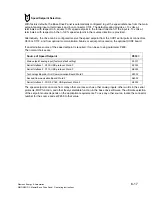
7
Selection of basic technological functions
7.1
Current
limits
P171
Motor current limit in torque direction I (in % of P100, default value = 100%)
US setting P171 = 150%
P172
Motor current limit in torque direction II (in % of P100, default value = -100%)
US setting P172 = -150%
7.2
Ramp-function
generator
P303
Acceleration time 1 (in seconds, default value = 10)
P304
Deceleration time 1 (in seconds, default value = 10)
P305
Initial rounding 1 (in seconds, default value = 0)
P306
Final rounding 1 (in seconds, default value = 0)
Summary of Contents for 6RA70 Series
Page 9: ...1 4 Siemens Energy Automation SIMOREG DC Master Base Drive Panel Operating Instructions NOTES ...
Page 25: ...4 2 Siemens Energy Automation SIMOREG DC Master Base Drive Panel Operating Instructions NOTES ...
Page 31: ...5 6 Siemens Energy Automation SIMOREG DC Master Base Drive Panel Operating Instructions NOTES ...


