7
05.01
7.3 Overcurrent protective devices, transformers and main switch
7-223
©
Siemens AG 2012 All Rights Reserved
SIMODRIVE 611 Configuration Manual (PJU) – 02/2012 Edition
Table 7-9
Autotransformer for a 220 V input voltage, continued
I/RF module
120/156
kW
I/RF module
80/104 kW
I/RF module
55/71 kW
I/RF module
36/47 kW
I/RF module
16/21 kW
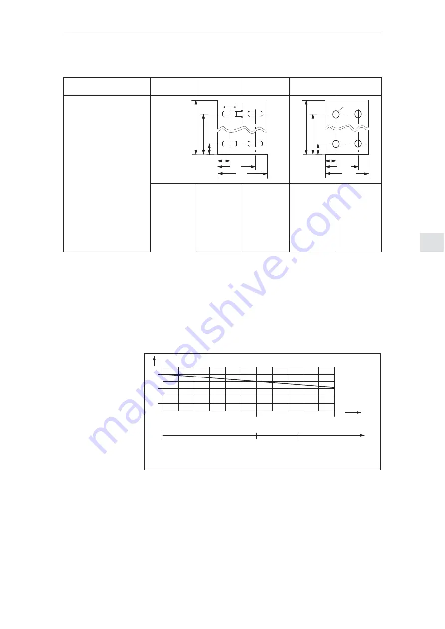
Max. dimensions
Drilling template in mm
Footprint, view from the top
t3
b4
t4
t1
t2
b3
b2
b1
t3
t1
t2
b
3
b2
b1
d
1
t1 = 370/460
t2 = 317
t3 = 53
t4 = 10
b1 = 220/465
b2 = 179
b3 = 41
b4 = 18
Height 330/555
t1 = 480/565
t2 = 418
t3 = 62
t4 = 15
b1 = 230/460
b2 = 205
b3 = 50
b4 = 22
Height 430/520
t1 = 480/565
t2 = 418
t3 = 62
t4 = 15
b1 = 300/460
b2 = 241
b3 = 59
b4 = 22
Height 430/520
t1 = 530/900
t2 = 470
t3 = 60
b1 = 290/600
b2 = 254
b3 = 71
d1 = 12.5
Height 520/720
t1 = 590/900
t2 = 530
t3 = 60
b1 = 320/600
b2 = 279
b3 = 81
d1 = 15
Height 585/720
1) Not IP20
2) 10% power derating required
3) FL = flat termination, hole
∅
9 mm
The permissible current of the transformers, reactors etc. depends on the ambi-
ent temperature and the installation altitude. The permissible current/power rat-
ing of transformers and reactors is as follows:
I
n
(PD) reduced = c
I
n
(PD)
1.1
0.9
0.7
40
50
C
m above sea level
1000
2000
c
a)
b)
a) The ambient temperature from +40
C
b) The installation altitude from 1000 m
Reduction factor c
as a function of:
30
Fig. 7-9
Reduction factor (derating) c
Operating
conditions
for all transformers
7 Line Supply Connection
10.04


