8
05.01
8.5 Start inhibit in the drive modules/safe standstill
8-258
©
Siemens AG 2012 All Rights Reserved
SIMODRIVE 611 Configuration Manual (PJU) – 02/2012 Edition
8.5.6
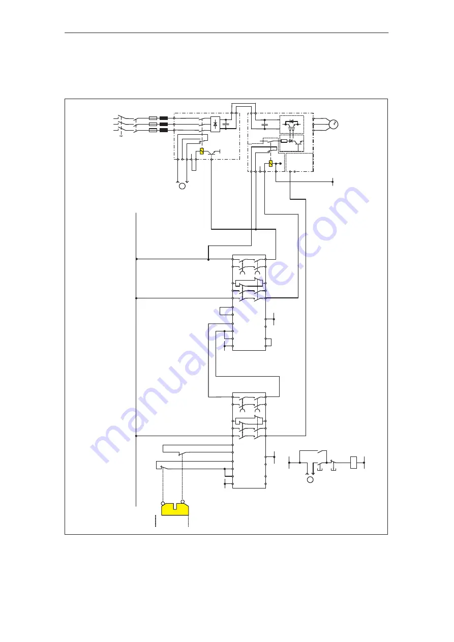
Example ”safe standstill” with contactor safety combination
–Q1
Main switches
Supply system
EN+
AS1
AS2
663
9
M
PV
SIMODRIVE
Closed–loop Control Module
U2
V2
W2
65
M
3
RF
n = 0
EN+
11
3
213
EN–
U1
V1
W1
111
48
NS1
NS2
SIMODRIVE
NE
Closed
Open
A1
Y10
Y21
Y22
Y1
1
Y12
13
14
3TK2828
24
23
31
47
57
32
48
58
Y33
Y34
PE
A2
A1
Y10
Y1
1
Y12
Y21
Y22
13
14
3TK2828
24
23
31
47
57
32
48
58
Y33
Y34
PE
A2
IF
M
M
P24
P24
P24
–A1
–A2
–S2
–S3
EN–
19
M
–S1
–K1
–K1
–S2
On
Of
f
1
Monitoring the internal
line contactor of the
Infeed unit
–K1
M
P24
1
Monitoring the internal
line contactor of the
Infeed unit
Line supply
Line supply
Fig. 8-9
Example, minimum circuitry for the ”safe standstill” function with SIMODRIVE 611
8 Important Circuit Information
02.03


