On-Line Operation
UMSITRPDS3-1
November
2010
6-22
1.
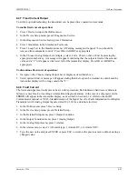
Install and pipe the transmitter. Ventilate or evacuate the transmitter.
•
Ventilate for pressure, differential pressure, flow, and flanged level transmitters.
•
Evacuate for absolute transmitters to <0.1% of the measuring span.
2.
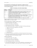
In the Online menu, press 3 Device Setup on the HART Communicator.
3.
Press 3 Basic Setup in the Device Setup menu.
4.
In the Basic Setup menu, press 3 Position Correction. A warning will appear: “Loop should be
removed from automatic control.” Press the ABORT or OK softkey as appropriate.
5.
A second warning will appear: “This will affect sensor calibration.”
6.
The message “Apply 0 input [atmospheric pressure] the sensor” will appear. Press ABORT or OK as
appropriate.
7.
A “correction successful” message will appear followed by a Loop may be returned to automatic
control message.
6.4.5 Electric Damping
Electric damping can be adjusted within the range of 0 to 100 seconds.
1.
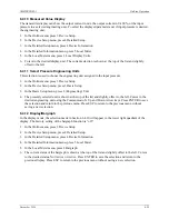
Press 3 Device Setup in the Online menu.
2.
Press 3 Basic Setup in the Device Setup menu.
3.
Press 6 Damping in the Basic Setup menu or cursor down, using the down arrow, to 6 Damp. Type a
new damping value and press ENTER. Press ESC to exit the display without making any changes.
6.4.6 Fast Measured Value Acquisition (fast response mode)
This mode is designed exclusively for special applications such as fast acquisition of pressure spikes, such
as a compressor surge. Here, the internal measured value acquisition is accelerated at the cost of accuracy.
There is an increase in low-frequency noise in the measured value. For best accuracy, configure the
transmitter for use at its maximum measuring span.
1.
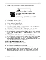
Press 3 Device Setup in the Online menu.
2.
Press 4 Detailed Setup in the Device Setup menu.
3.
Press 2 Signal Condition in the Detailed Setup menu.
4.
Press 6 Measuring Speed in the Signal Condition menu.
5.
Use the arrow pushbuttons to select: Fast, Medium, or Slow.
6.
Press the ENTER softkey to save the selection and return to the Signal Condition menu.
Summary of Contents for 7MF4033 series
Page 48: ...Model 275 Universal Hart Communicator UMSITRPDS3 1 November 2010 2 26 ...
Page 86: ...Installation UMSITRPDS3 1 November 2010 4 34 ...
Page 152: ...Calibration and Maintenance UMSITRPSD3 1 November 2010 7 20 ...
Page 158: ...Circuit Description UMSITRPDS3 1 November 2010 8 6 ...
Page 197: ......
Page 198: ......
Page 200: ...Model Designations and Specifications UMSITRPDS3 1 November 2010 9 42 ...
Page 204: ...Glossary UMSITRPDS3 1 November 2010 10 4 ...
Page 208: ...Appendix A Online Configuration Map UMSITRPDS3 1 11 4 November 2010 ...
Page 216: ...Appendix C Elevation and Suppression Correction UMSITRPDS3 1 13 4 November 2010 ...


