On-Line Operation
UMSITRPDS3-1
November
2010
6-26
6.4.13 Sensor Trim
Using sensor trim it is possible to set the characteristic of the transmitter at two adjustment points. This
has the effect of improving the measurement accuracy by setting the sensor’s upper and lower values
close to the range of process pressure values. The adjustment points are freely selectable within the
sensor’s nominal range.
Transmitters not turned down at the factory are adjusted at 0 psi and the nominal upper range limit. Those
turned down at the factory are adjusted at the lower and upper limits of the set measuring range.
Application Examples:
•
If the desired span is 725 psi for a transmitter with a maximum pressure of 925 psi, then to achieve
the greatest possible accuracy for this value, make the upper sensor adjustment at 725 psi.
•
A 925 psi transmitter is turned down to 58 to 101.5 psi. To achieve the greatest possible accuracy,
make the lower sensor adjustment point at 58 psi and the upper adjustment point 101.5 psi.
Note
Pressure sources must be sufficiently accurate.
Either of the trimming procedures below can be cancelled without storing a new trim setting by pressing
ABORT. The factory trims can be restored in the Diagnostics/Service menu. Refer to the Online
Configuration Map in Appendix A.
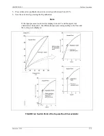
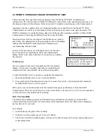
6.4.13.1 Trimming the Lower Sensor Adjustment Point
In this procedure, the reference pressure representing the lower sensor adjustment point is applied and the
transmitter is instructed to accept this pressure. This represents an offset shift of the characteristic, as
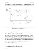
shown in Figure 6-4.
1.
Apply a reference pressure representing the lower sensor adjustment point.
2.
In the Online menu, press 3 Device Setup.
3.
In the Device Setup menu, press 2 Diagnostics/Service.
4.
In the Diagnostics/Service menu, press 4 Trim.
5.
In the Trim menu press, 2 Sensor Trim.
6.
In the Sensor Trim menu, press 3 Lower Sensor Trim. A warning message will appear: “Loop should
be removed from automatic control.” Take the appropriate action and press OK to continue. A second
warning will appear: “This will affect sensor calibration.” Again, press OK to continue.
7.
The “Apply low pressure” message will appear. Press OK to continue. A “Pressure OK when pressure
is stable” message will appear. Press OK to continue.
8.
The applied value is displayed next. The value can be changed from the Communicator’s keyboard.
Press ENTER to store the value or press ABORT to exit the procedure without storing a value.
9.
Remove the reference pressure or go to the next section to set the upper sensor adjustment point.
Summary of Contents for 7MF4033 series
Page 48: ...Model 275 Universal Hart Communicator UMSITRPDS3 1 November 2010 2 26 ...
Page 86: ...Installation UMSITRPDS3 1 November 2010 4 34 ...
Page 152: ...Calibration and Maintenance UMSITRPSD3 1 November 2010 7 20 ...
Page 158: ...Circuit Description UMSITRPDS3 1 November 2010 8 6 ...
Page 197: ......
Page 198: ......
Page 200: ...Model Designations and Specifications UMSITRPDS3 1 November 2010 9 42 ...
Page 204: ...Glossary UMSITRPDS3 1 November 2010 10 4 ...
Page 208: ...Appendix A Online Configuration Map UMSITRPDS3 1 11 4 November 2010 ...
Page 216: ...Appendix C Elevation and Suppression Correction UMSITRPDS3 1 13 4 November 2010 ...


