UMSITRPDS3-1
Introduction
November 2010
1-1
1.0 INTRODUCTION
This user’s manual is for the Siemens SITRANS P Series DSIII Pressure Transmitters.
All information needed to bench test, install, configure, calibrate, and service a transmitter is included in
this user’s manual.
IMPORTANT
Save this user’s manual. It should be available to those installing, configuring,
operating, and servicing the described pressure transmitters.
1.1 CONTENTS
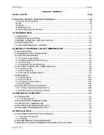
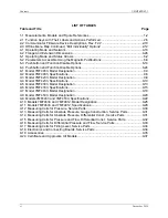
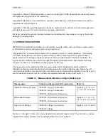
The user’s manual consists of a table of contents, ten sections, and three appendices. Following the table
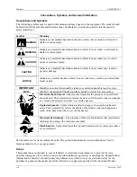
of contents is a subsection that contains important information about the symbols that can appear in this
user’s manual and on the transmitter. The subsection also has statements about installing and servicing the
transmitter. A brief description of each major section and appendices follows.
Section 1, Introduction, describes each section in the manual and provides a brief description of the
SITRANS P Series DSIII Pressure Transmitter line. A product support section has telephone, fax, E-mail,
and Internet contact information.
Section 2, Model 275 Universal HART Communicator, describes use of the HART Communicator to test,
configure, and calibrate a transmitter.
Section 3, Pre-Installation Test, provides procedures to perform a bench test of the transmitter to ensure
proper operation of all transmitter functions. Start-up configuration is described here.
Section 4, Installation, furnishes specific information for mechanical and electrical installation of the
transmitter.
Section 5, Post-Installation Test, describes how to confirm that the transmitter has been installed correctly
- sometimes referred to as commissioning.
Section 6, On-Line Configuration and Operation, details local configuration using the magnetic
pushbuttons and remote configuration using the HART Communicator. Local operation and remote
operation of the transmitter are described.
Section 7, Calibration and Maintenance, provides references to calibration procedures for analog and
digital modes and to a zeroing procedure for mounting position. It also furnishes preventive maintenance,
troubleshooting, and assembly replacement procedures.
Section 8, Circuit Description, contains an assembly-level circuit description to support transmitter
servicing.
Section 9, Model Designations and Specifications, has tables that correlate rating plate model numbers to
transmitter physical configurations. This section also contains an accessory list and several service parts
lists. Detailed mechanical, functional, performance, and environmental specifications are provided, as are
dimension drawings of the transmitter. Hazardous area certifications are listed.
Section 10, Glossary, contains definitions of various transmitter-related terms.
Summary of Contents for 7MF4033 series
Page 48: ...Model 275 Universal Hart Communicator UMSITRPDS3 1 November 2010 2 26 ...
Page 86: ...Installation UMSITRPDS3 1 November 2010 4 34 ...
Page 152: ...Calibration and Maintenance UMSITRPSD3 1 November 2010 7 20 ...
Page 158: ...Circuit Description UMSITRPDS3 1 November 2010 8 6 ...
Page 197: ......
Page 198: ......
Page 200: ...Model Designations and Specifications UMSITRPDS3 1 November 2010 9 42 ...
Page 204: ...Glossary UMSITRPDS3 1 November 2010 10 4 ...
Page 208: ...Appendix A Online Configuration Map UMSITRPDS3 1 11 4 November 2010 ...
Page 216: ...Appendix C Elevation and Suppression Correction UMSITRPDS3 1 13 4 November 2010 ...


