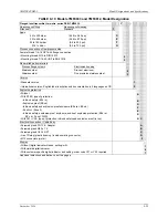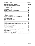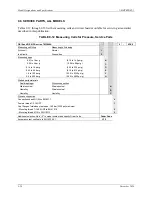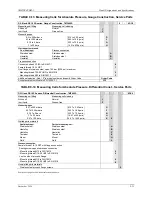
Model Designations and Specifications
UMSITRPDS3-1
November
2010
9-38
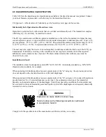
Comply with your country’s laws and regulations that apply to electrical installation in an explosive
environment.
Be sure that the available power supply complies with the specifications on the transmitter rating plate
and statements in the examination certificate in your country. Dust-proof protection caps in the cable
inlets must be replaced by suitable screw-type gland or dummy plugs that must be appropriately certified
for transmitters with explosion proof type of protection.
9.9.1 CSA Hazardous Locations Precautions
This section provides CSA hazardous location precautions that should be observed by the user when
installing or servicing the equipment described in this manual. These statements supplement those given
in the preceding section.
WARNING
Explosion can cause death or serious injury.
Failure to observe the following precautions could result
in an explosion hazard.
Precautions - English
For Class I, Division 1 and Class I, Division 2 hazardous locations:
•
Use only factory-authorized replacement parts. Substitution of components can impair the suitability
of this equipment for hazardous locations.
For Division 2 hazardous locations:
When the equipment described in this Instruction in installed without safety barriers, the following
precautions should be observed. Switch off electrical power at its source (in non-hazardous location)
before connecting or disconnecting power, signal, or other wiring.
Précautions - Français
Emplacements dangereux de classe I, division 1 et classe I, division 2:
•
Les pièces de rechange doivent être autorisées par l’usine. Les substitutions peuvent rendre cet
appareil impropre à l’utilisation dans les emplacements dangereux.
Emplacement dangereux de division 2:
Lorsque l’appareil décrit dans la notice ci-jointe est installé sans barrières de sécurité, on doit couper
l’alimentation électrique a la source (hors de l’emplacement dangereux) avant d’effectuer les opérations
suivantes branchment ou débranchement d’un circuit de puissance, de signalisation ou autre.
Summary of Contents for 7MF4033 series
Page 48: ...Model 275 Universal Hart Communicator UMSITRPDS3 1 November 2010 2 26 ...
Page 86: ...Installation UMSITRPDS3 1 November 2010 4 34 ...
Page 152: ...Calibration and Maintenance UMSITRPSD3 1 November 2010 7 20 ...
Page 158: ...Circuit Description UMSITRPDS3 1 November 2010 8 6 ...
Page 197: ......
Page 198: ......
Page 200: ...Model Designations and Specifications UMSITRPDS3 1 November 2010 9 42 ...
Page 204: ...Glossary UMSITRPDS3 1 November 2010 10 4 ...
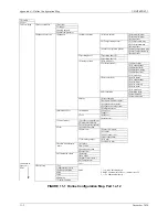
Page 208: ...Appendix A Online Configuration Map UMSITRPDS3 1 11 4 November 2010 ...
Page 216: ...Appendix C Elevation and Suppression Correction UMSITRPDS3 1 13 4 November 2010 ...


