UMSITRPDS3-1
Model 275 Universal Hart Communicator
November 2010
2-1
2.0 MODEL 275 UNIVERSAL HART COMMUNICATOR
The Model 275 Universal HART Communicator is a handheld interface that provides a common
communication link to SITRANS P transmitters and other HART-compatible instruments.
This section describes HART Communicator connections, liquid crystal display, keypad, and on-line and
off-line menus. It also provides overviews of many Communicator functions. The Communicator is
shown in Figure 2-1. For information about the Communicator’s battery pack, Memory Module, Data
Pack, and maintenance procedures, refer to the manual supplied with the Communicator.
2.1 INTRODUCTION
The HART Communicator connects to and communicates with a transmitter or other HART device using
a 4-20 mA loop, provided a minimum load resistance of 250
Ω
is present between the Communicator and
the power supply. The Communicator uses Bell 202 frequency-shift keying (FSK) to impose high-
frequency digital signals on a standard 4-20 mA current loop. Because no net energy is added to the loop,
HART communication does not disturb the 4-20 mA signal.
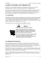
The Communicator can be used in hazardous and non-hazardous locations.
WARNING
Explosion can cause death or serious injury.
Before connecting the HART Communicator in an
explosive atmosphere, be sure that the instruments in
the loop are installed in accordance with intrinsically
safe or non-incendive field wiring practices.
Refer to the Communicator nameplate and the supplied
manual for certifications and approvals before
connecting, or making a connection to the serial port or
NiCad charger port on the Communicator.
2.2 COMMUNICATOR CONNECTIONS
The Communicator can interface with a transmitter from the control room, the instrument site, or any
wiring termination point in the loop. Connections are made through a supplied 40" (1m) cable (dual
banana plug to mini-hook test clips). The connection panel also may have a jack for the optional NiCad
charger, and it has a serial port for a future connection to a personal computer (PC).
To interface with a transmitter or other HART device, connect the HART Communicator in parallel with
the instrument or load resistor. The connections are non-polar. For intrinsically safe FM and CSA wiring
connections, see the manual supplied with the Communicator.
Figure 2-2 illustrates typical wiring connections between the HART Communicator and a loop with a
transmitter or other HART-compatible device in a loop. The Communicator is quickly connected into a
transmitter loop.
Summary of Contents for 7MF4033 series
Page 48: ...Model 275 Universal Hart Communicator UMSITRPDS3 1 November 2010 2 26 ...
Page 86: ...Installation UMSITRPDS3 1 November 2010 4 34 ...
Page 152: ...Calibration and Maintenance UMSITRPSD3 1 November 2010 7 20 ...
Page 158: ...Circuit Description UMSITRPDS3 1 November 2010 8 6 ...
Page 197: ......
Page 198: ......
Page 200: ...Model Designations and Specifications UMSITRPDS3 1 November 2010 9 42 ...
Page 204: ...Glossary UMSITRPDS3 1 November 2010 10 4 ...
Page 208: ...Appendix A Online Configuration Map UMSITRPDS3 1 11 4 November 2010 ...
Page 216: ...Appendix C Elevation and Suppression Correction UMSITRPDS3 1 13 4 November 2010 ...


