Installation
UMSITRPDS3-1
November
2010
4-14
4.3.4.2 Digital Mode
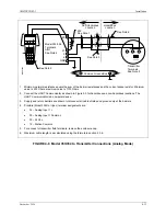
When a transmitter is configured for digital mode operation, the following statements apply.
•
Process and configuration data are transmitted digitally. The analog output of each transmitter is
“parked” at 4 mA.
•
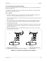
Employs a Multi-Drop network. See Figure 4-9.
•
The optional display can be used for local indication of transmitter output.
The number of allowable network elements is:
–
Primary and Secondary Masters - 1 each
–
Transmitters - 1 to 15
•
The HART communication source can be a Primary or Secondary Master. A Primary Master can be
used for data acquisition, maintenance, or control purposes. A Secondary Master, the HART
Communicator, for example, may be used for configuration, diagnostics, and reporting current
process variable.
•
Place the transmitter in the digital mode by assigning it a polling address (1 to 15) with the HART
Communicator (see Section 6).
•
Each transmitter connected to a network must have a unique address.
4.3.5 Power Supply Requirements
A power supply
is needed to power the transmitter(s). The power supply can be:
•
A separate stand-alone supply capable of powering several transmitters. It can be mounted in a
control room or in the field. Follow the power supply manufacturer’s recommendations with regard to
mounting and environmental considerations.
•
Located in a controller (such as a Primary Master) or other station able to safely provide additional
operating current and meet the power supply specifications of Section 9.3.
Determine needed power supply output voltage by calculating the Network Resistance and consulting
Figure 4-10. It shows the minimum power supply voltage needed for the calculated Network Resistance.
The total Network Resistance is the sum of the Current Sense Resistance, end-to-end Barrier Resistance
(if used), wire resistance, and any other resistances in the loop. The minimum Network Resistance (see
Section 10 Glossary) required to support HART communications is 250
Ω
. The maximum resistance is
1100
Ω
. Refer to Section 4.3.5.1 or 4.3.5.2 for calculations.
1
An SELV (Separated Extra-Low Voltage) power supply is suggested; see IEC 364-1 and IEC 536.
Summary of Contents for 7MF4033 series
Page 48: ...Model 275 Universal Hart Communicator UMSITRPDS3 1 November 2010 2 26 ...
Page 86: ...Installation UMSITRPDS3 1 November 2010 4 34 ...
Page 152: ...Calibration and Maintenance UMSITRPSD3 1 November 2010 7 20 ...
Page 158: ...Circuit Description UMSITRPDS3 1 November 2010 8 6 ...
Page 197: ......
Page 198: ......
Page 200: ...Model Designations and Specifications UMSITRPDS3 1 November 2010 9 42 ...
Page 204: ...Glossary UMSITRPDS3 1 November 2010 10 4 ...
Page 208: ...Appendix A Online Configuration Map UMSITRPDS3 1 11 4 November 2010 ...
Page 216: ...Appendix C Elevation and Suppression Correction UMSITRPDS3 1 13 4 November 2010 ...


