Installation
UMSITRPDS3-1
November
2010
4-30
4.5.3.2 Cables
•
Mark or tag each cable conductor as either LOOP (+) or LOOP (-) to ensure correct connection at the
transmitter.
•
Use pulling grips and cable lubricants for easier cable pulling. Pull cable through conduit into
transmitter terminal compartment.
•
Do not exceed the maximum permitted pulling tension on the cables. Maximum tension is normally
specified as 40% of the cable’s breaking strength.
•
Do not exceed the maximum conduit fill specified by the National Electric Code.
4.5.3.3 Access to Transmitter Terminal Compartment
1.
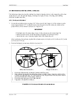
Remove the enclosure cap closest to the electrical entrance by turning it counterclockwise.
2.
Install the enclosure cap by turning it clockwise until the O-ring contact the enclosure. Tighten the
cap one additional turn to compress the O-ring.
Summary of Contents for 7MF4033 series
Page 48: ...Model 275 Universal Hart Communicator UMSITRPDS3 1 November 2010 2 26 ...
Page 86: ...Installation UMSITRPDS3 1 November 2010 4 34 ...
Page 152: ...Calibration and Maintenance UMSITRPSD3 1 November 2010 7 20 ...
Page 158: ...Circuit Description UMSITRPDS3 1 November 2010 8 6 ...
Page 197: ......
Page 198: ......
Page 200: ...Model Designations and Specifications UMSITRPDS3 1 November 2010 9 42 ...
Page 204: ...Glossary UMSITRPDS3 1 November 2010 10 4 ...
Page 208: ...Appendix A Online Configuration Map UMSITRPDS3 1 11 4 November 2010 ...
Page 216: ...Appendix C Elevation and Suppression Correction UMSITRPDS3 1 13 4 November 2010 ...


