Introduction
UMSITRPDS3-1
November
2010
1-2
Appendix A, Online Configuration Map, is used to help navigate HART/transmitter menus during remote
configuration and operation of the transmitter.
Appendix B, Hazardous Area Installations, contains control drawings and other information needed for
installation in a hazardous area.
Appendix C, Elevation and Suppression Corrections, explains how to perform elevation and suppression
calculations necessary for certain liquid level gauging applications.
Warranty contains the product warranty statements and information concerning servicing of the product
during the warranty period.
1.2 PRODUCT DESCRIPTION
SITRANS P Series DSIII transmitters provide reliable, accurate, stable, and cost-effective measurement
of differential, absolute, and gauge pressure and liquid level.
The transmitter is a microcontroller-based, self-contained pressure-to-current transducer. A measuring
cell senses the applied process pressure and provides an analog output signal that is proportional to
applied pressure. An analog-to-digital converter produces a digital signal for the microcontroller. The
microcontroller modifies and corrects the signal for linearity and temperature, and a digital-to-analog
converter produces a 4-20 milliampere output signal for the loop.
The transmitter can be installed quickly and easily using one of the optional mounting brackets.
Illustrations showing mounting hardware and dimensions are provided in this manual. Measuring cell
construction determines a transmitter’s physical dimensions and mechanical installation. Note that a given
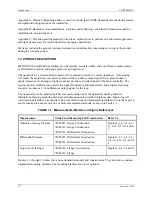
sensor construction can involve one or more measurement methods, as shown in Table 1-1.
TABLE 1-1 Measurements, Models and Figure References
Measurement
Model And Measuring Cell Construction
Refer To
Absolute or Gauge Pressure
7MF4033, Gauge Construction
7MF4233, Gauge Construction
7MF4333, Differential Construction
Figures 1-1, 4-3, 4-4, 4-
11, 4-13, 9-1, 9-2 and 9-
3
Differential Pressure
7MF4433, Differential Construction
7MF4533, Differential Construction
Figures 1-2, 1-3, 4-1, 4-
2, 4-12, 4-13, 9-3, and 9-
4
Liquid Level (Flange)
7MF4633, Flange Construction
7MF4812, Flange
Figures 1-4, 4-5, and 9-5
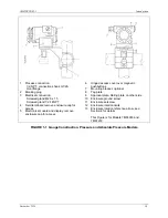
Figures 1-1 through 1-4 show the various transmitter models and constructions. They also show common
transmitter mounting methods. The mounting brackets shown are optional.
Summary of Contents for 7MF4033 series
Page 48: ...Model 275 Universal Hart Communicator UMSITRPDS3 1 November 2010 2 26 ...
Page 86: ...Installation UMSITRPDS3 1 November 2010 4 34 ...
Page 152: ...Calibration and Maintenance UMSITRPSD3 1 November 2010 7 20 ...
Page 158: ...Circuit Description UMSITRPDS3 1 November 2010 8 6 ...
Page 197: ......
Page 198: ......
Page 200: ...Model Designations and Specifications UMSITRPDS3 1 November 2010 9 42 ...
Page 204: ...Glossary UMSITRPDS3 1 November 2010 10 4 ...
Page 208: ...Appendix A Online Configuration Map UMSITRPDS3 1 11 4 November 2010 ...
Page 216: ...Appendix C Elevation and Suppression Correction UMSITRPDS3 1 13 4 November 2010 ...


