UMSITRPDS3-1
Introduction
November 2010
1-3
1
2
3
4
5
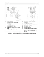
Process connection:
1/2-NPT, connection shank G1/2A
Oval flange
Blanking plug
Electrical connection:
Screwed gland M20 x 1.5
Screwed gland 1/2-14NPT
Field terminals; remove enclosure cap for
access
Electronics module and display; remove
enclosure cap for access
6
7
8
9
10
11
12
13
Hinged access cover over magnetic
pushbuttons
Mounting bracket, optional
Tag plate
Approval plate; Rating plate on other side
Enclosure ground screw
Enclosure setscrew
Enclosure rotation limits
Enclosure rotation reference arrow; see
Section 4 for details
This Figure is for Models 7MF4033 and
7MF4233
FIGURE 1-1 Gauge Construction, Pressure and Absolute Pressure Models
Summary of Contents for 7MF4033 series
Page 48: ...Model 275 Universal Hart Communicator UMSITRPDS3 1 November 2010 2 26 ...
Page 86: ...Installation UMSITRPDS3 1 November 2010 4 34 ...
Page 152: ...Calibration and Maintenance UMSITRPSD3 1 November 2010 7 20 ...
Page 158: ...Circuit Description UMSITRPDS3 1 November 2010 8 6 ...
Page 197: ......
Page 198: ......
Page 200: ...Model Designations and Specifications UMSITRPDS3 1 November 2010 9 42 ...
Page 204: ...Glossary UMSITRPDS3 1 November 2010 10 4 ...
Page 208: ...Appendix A Online Configuration Map UMSITRPDS3 1 11 4 November 2010 ...
Page 216: ...Appendix C Elevation and Suppression Correction UMSITRPDS3 1 13 4 November 2010 ...


