Introduction
UMSITRPDS3-1
November
2010
1-8
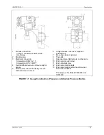
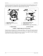
An enclosure ground connection is located on the housing beneath the field terminal enclosure cap. The
enclosure should always be grounded by a wire connected from this terminal to an earth ground, even
when a ground may be provided by metal conduit protecting the loop wiring.
+
+
MG
00364b
1
2
3
MG
00364b
-4-20mA+
_
+
1
2
3
4
4
1
2
3
Digital display, optional
Magnetic pushbutton access cover
Enclosure cap
1
2
3
4
Field terminals for analog output
Analog output test terminals
Enclosure ground
Electrical entrances; plug unused entrance
A. Digital Display
B. Field Terminals
FIGURE 1-6 Digital Display and Field Terminals
Transmitters have an intrinsically safe, explosion proof, NEMA 4x (IP67/68), field mountable, hardened
enclosure. Electrical conduit connections are 1/2-14 NPT or M20 x 1.5. All process wetted materials are
316 stainless steel or better. The flush-mount process connection of the liquid level model is compatible
with standard ANSI and metric flange sizes for tanks and pipes.
Summary of Contents for 7MF4033 series
Page 48: ...Model 275 Universal Hart Communicator UMSITRPDS3 1 November 2010 2 26 ...
Page 86: ...Installation UMSITRPDS3 1 November 2010 4 34 ...
Page 152: ...Calibration and Maintenance UMSITRPSD3 1 November 2010 7 20 ...
Page 158: ...Circuit Description UMSITRPDS3 1 November 2010 8 6 ...
Page 197: ......
Page 198: ......
Page 200: ...Model Designations and Specifications UMSITRPDS3 1 November 2010 9 42 ...
Page 204: ...Glossary UMSITRPDS3 1 November 2010 10 4 ...
Page 208: ...Appendix A Online Configuration Map UMSITRPDS3 1 11 4 November 2010 ...
Page 216: ...Appendix C Elevation and Suppression Correction UMSITRPDS3 1 13 4 November 2010 ...


