Pre-Installation Test
UMSITRAPDS3-1
November
2010
3-2
_
+
mA
+
_
- +
4-20 mA
+
I
O
250
+
_
_
MG
00358b
Vdc
1
2
3
4
5
6
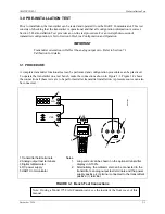
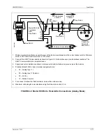
1 Transmitter field terminals
2 Analog output terminals
3 Digital milliammeter
4 HART Communicator
5 Controller, recorder, indicator, or other 1-5 Vdc device
6 DC power supply
Note: Loop current can also be shown on the optional transmitter
display in 0-100%.
FIGURE 3-2 Field Test Connections
3.1.1 Test Equipment
TEST EQUIPMENT
DESCRIPTION
(see Specifications, Section 9.3)
Power Supply
10.5 to 45 Vdc, see Power Supply Requirements, Section 4.3.5
Multimeter:
Current
Range: 4 to 20 mA to measure loop current
Voltage
Range: 0-50 Vdc to measure power supply and loop voltage
Current Sense Resistor 250 to 1100
Ω
to support HART digital communications
Configuration Device
Model 275 HART Communicator or Model 375 Field Communicator
Pressure Source
Dead Weight Tester or similar device.
Note
Test equipment should be 2 to 10 times more accurate than the transmitter
accuracy.
Summary of Contents for 7MF4033 series
Page 48: ...Model 275 Universal Hart Communicator UMSITRPDS3 1 November 2010 2 26 ...
Page 86: ...Installation UMSITRPDS3 1 November 2010 4 34 ...
Page 152: ...Calibration and Maintenance UMSITRPSD3 1 November 2010 7 20 ...
Page 158: ...Circuit Description UMSITRPDS3 1 November 2010 8 6 ...
Page 197: ......
Page 198: ......
Page 200: ...Model Designations and Specifications UMSITRPDS3 1 November 2010 9 42 ...
Page 204: ...Glossary UMSITRPDS3 1 November 2010 10 4 ...
Page 208: ...Appendix A Online Configuration Map UMSITRPDS3 1 11 4 November 2010 ...
Page 216: ...Appendix C Elevation and Suppression Correction UMSITRPDS3 1 13 4 November 2010 ...

