Installation
UMSITRPDS3-1
November
2010
4-2
4.2 ENVIRONMENTAL CONSIDERATIONS
Many industrial processes create severe environmental conditions. The conditions at each transmitter
location must be within the specifications stated in Section 9.3 Specifications.
Although the transmitter is designed to perform in harsh conditions, it is prudent to choose a location that
minimizes the effects of heat, vibration, shock, and electrical interference.
CAUTION
Exceeding the specified operating temperature limits can adversely affect
performance and may damage the instrument. See the rating plate and Section 9
Model Designations and Specifications for temperature and other environmental
ratings.
4.3 PRE-INSTALLATION CONSIDERATIONS AND CALCULATIONS
These sub-sections provide pre-installation considerations and calculations that are needed to ensure
successful mechanical and electrical installations.
4.3.1 Mechanical
•
Select the application. Series DSIII transmitters are suitable for, but not limited to:
•
Flow measurement
•
Gauge pressure measurement
•
Level measurement
•
Draft pressure measurement
•
Absolute pressure measurement
•
High differential pressure measurement
•
Hydrostatic tank gauging measurement
•
Determine the physical mounting of the transmitter. Consider:
•
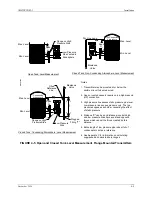
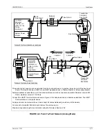
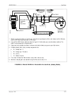
Application – See Figures 4-1 through 4-5. Mounting position for a specific application can be
important to system performance.
•
Optional brackets for pipe mounting or surface mounting
•
Pipe or tank wall thickness, diameter, rigidity, and freedom from vibration
•
Clearance for transmitter installation and maintenance
•
Need to rotate the enclosure and display for viewing ease
Refer to Figures 9-1 through 9-4 for transmitter dimensions and to the figures in Sections 4.4 and 4.5
for typical mechanical installations. Refer to Section 9.3 for mechanical and environmental
specifications.
Summary of Contents for 7MF4033 series
Page 48: ...Model 275 Universal Hart Communicator UMSITRPDS3 1 November 2010 2 26 ...
Page 86: ...Installation UMSITRPDS3 1 November 2010 4 34 ...
Page 152: ...Calibration and Maintenance UMSITRPSD3 1 November 2010 7 20 ...
Page 158: ...Circuit Description UMSITRPDS3 1 November 2010 8 6 ...
Page 197: ......
Page 198: ......
Page 200: ...Model Designations and Specifications UMSITRPDS3 1 November 2010 9 42 ...
Page 204: ...Glossary UMSITRPDS3 1 November 2010 10 4 ...
Page 208: ...Appendix A Online Configuration Map UMSITRPDS3 1 11 4 November 2010 ...
Page 216: ...Appendix C Elevation and Suppression Correction UMSITRPDS3 1 13 4 November 2010 ...


