7PG21 Solkor Rf Installation
1
Unpacking, storage and handling
On receipt, remove the relay(s) from the container in which it was received and inspect it for obvious damage.
Check that the relay(s) is the correct model number and the rating information is correct. It is recommended that
the relay is not removed from the case. To prevent the possible ingress of dirt, the sealed polythene bag should
not be opened until the relay is to be used. If damage has been sustained a claim should immediately be made
against the carrier and the local Siemens office should be informed, using the Defect Report Form in the
Maintenance section of this manual.
When not required for immediate use the relay should be returned to its original carton and stored in a clean, dry
place.
2 Recommended Mounting Position
The Solkor Rf relay has test points fitted for use during commissioning and routine testing and a mechanical flag
as a visual indication of relay operation. The relay should be mounted onto the circuit breaker or panel at a level
which allows the user easiest access to the relay functions.
Components which have 15kV isolated pilot connections are often mounted separately from the protection relay
in a location more convenient for the connection to the incoming pilot cable and/or in the interest of safety.
Connections to the relay can then be made at the lower 5kV insulation level with precautions and identification
to suit.
3 Relay Dimensions
The Solkor Rf relay is supplied in an Epsilon size E6 case.
5kV Pilot Supervision Send and Receive End units are supplied in Epsilon size E4 case.
B22 Supply Supervision relay, B74 repeat relay for use with 15kV Receive relay (B75) and the B34 relay for Rf
Intertripping are each supplied in an Epsilon size E2 case
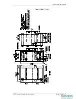
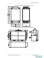
Mechanical diagrams of the Epsilon case dimensions and panel cut-out requirements are shown in Figures 1-3.
15kV Send End, B75 Receive relays and the TEC intertripping relay are supplied in Vedette size 1 1/2V case.
Mechanical diagrams of case dimensions and panel cut-out requirements are shown in Figure 4.
The Intertripping Inverter is supplied in a special case for back of panel mounting and Mechanical diagrams of
case dimensions and mounting requirements are shown in Figure 5.
The 15Kv Isolation Transformer is supplied in a special case for back of panel mounting and Mechanical
diagrams of case dimensions and mounting requirements are shown in Figure 6.
4
Fixings
4.1 Epsilon Cases
4.1.1 Crimps
M4 Ring tongued crimps with 90˚ bend are recommended.
©2010 Siemens Protection Devices Limited
Chapter 5 Page 3 of 7


