7SG11 Argus Technical Reference
©2013 Siemens Protection Devices Limited
P20007 Page 56 of 71
current. Based on the above considerations the minimum setting of a relay in a resistance earthed power system
is 6 to 9 times the charging current per phase.
3.4 Blocking Schemes
Where substations in a radial network are physically close, such as on the MV system in a power station, and pilot
cables can be economically run between switchboards, the times set on a particular relay and an upstream relay
can be made identical. This reduces the fault clearance time by eliminating the grading margin delay. To achieve
this, the Overcurrent starter contact of the downstream relay is connected via pilot wires to Block (inhibit) the
upstream relay. Grading is ensured by this blocking feature provided that the upstream tripping time is set to be
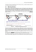
longer, with margin, than the time taken for the downstream blocking signal input to be raised. Figure 3.4-1
illustrates the scheme.
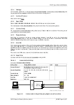
P300005 Application Diagrams / Blocking
HS1
50ms
DTL
HS1
50ms
DTL
Starter
Block
Starter
Block
Power Flow
Metallic connection required between relaying points
Starter output of downstream relay arranged to block (Inhibit) the next upstream HS1 characteristic via a Status
input
All upstream HS1 elements have same overcurrent setting plus HS1 Delay DTL of 50ms
IDMT protection not affected
Scheme can be arranged to provide pilot wire supervision (trip inhibit)
Radial System
Overcurrent
Protection
Relay
Overcurrent
Protection
Relay
Overcurrent
Protection
Relay
Figure 3.4-1
Blocking scheme giving fast fault clearance
This example shows the use of a “starter” output to block a Highset protection function for a circuit breaker nearer
to the source. Type tests have shown that with a time delay as low as 40ms on the upstream Highset function that
grading is ensured preventing the upstream relay instigating a trip. For security reasons a minimum time delay of
50ms is recommended, typically 100ms can be used. The Blocking Status input used to inhibit the HighSet
function should have 10ms Pick-up and Zero Drop-off delay settings to give fast operation but a.c. pick-up
rejection.
The example, shown in Figure 3.4-1, also proposes the use of IDMTL functions grading in the normal manner as
back-up protection for a down stream circuit, e.g. due to failure of the circuit breaker to clear a fault.
The combination of blocked lowset or Highset function and IDMTL back-up ensures fast operation for a circuit
fault and, provided the IDMTL grading has been correctly calculated and set, will also provide back-up protection.


