7SG11 Argus Technical Reference
©2013 Siemens Protection Devices Limited
P20007 Page 61 of 71
3.7.3 Shots to Lockout Setting
There are no strict guidelines for setting this parameter but a few factors need to be taken into consideration. The
recloser design should be taken into account and the system conditions should be examined as to the nature of
typical faults. If there is a sufficient percentage of semi-permanent faults which could be burnt away, e.g. fallen
branches, a multi shot scheme would be appropriate. Alternatively, if there is a likelihood of permanent faults, a
single shot scheme would provide a higher quality of supply.
3.7.4 Sequence Auto-reclosing
In Argus 4 & 6 auto-reclose Relays, the low-set overcurrent stage functions as the Instantaneous trip.
Complex sequences may be user programmed to give the best fault clearance strategy.
The Argus 4 and 6 relays provide auto-reclosing with sequence co-ordination of the Instantaneous low-set
characteristics and Shot Counters. The source low-set is time delayed (i.e. time delayed instantaneous and
grading and Sequence Co-ordination with a downstream instantaneous recloser is ensured. Typically, an auto-
reclose sequence set to 2 Instantaneous Trips plus one Delayed Trip will restore supplies for 90% of fault
conditions.
3.8 Trip Circuit Supervision
The Argus relay can be used to supervise one or more trip circuits, via status inputs, with the associated circuit
breaker open or closed. A low value of d.c. current is passed through the entire trip circuit to monitor the auxiliary
supply, the trip coil, its auxiliary switch, the C.B. secondary isolating contacts and the relevant wiring/links. If the
circuit develops a fault and monitoring current flow ceases, the normally energised status input drops off and if it
is user programmed to operate one of the output relays, then this relay gives a contact output to signal
Trip Circuit
Fail
. In addition, the LCD display on the Argus relay will indicate “Trip Circuit FAIL”.
To avoid giving spurious alarm messages while the circuit breaker is operating, the status input should be
programmed to have a 400 ms drop-off delay.
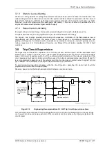
Schemes, based on the Electricity Association H6/H5 schemes, are shown below.
Figure 3.8-1
Engineering Recommendations S.15 H6 Trip Circuit Supervision scheme
This scheme provides continuous Trip Circuit Supervision of trip coil with circuit breaker Open or Closed. It does
not, however, provide pre-closing supervision of the connections and links between the tripping contacts and the
circuit breaker.
Argus relay
Trip contacts
Status input
-ve
Circuit breaker
+ve
For 110/125 VDC
use external 2K7
dropper resistor
with 48V status
input
Auxiliary contacts
Trip coil
P300005 Application Diagrams / TCS

