7SG11 Argus Technical Reference
©2013 Siemens Protection Devices Limited
P20007 Page 68 of 71
Laptop computer
P300007 Communications.vsd / Sigma 1
Sigma 1
F
ro
n
t
R
S
2
3
2
Control
System
up to 29 slaves (relays)
Rx
Tx
Rx
Tx
Rx
Tx
master
link
...
Auxiliary supply
Tx
Rx
Tx
Rx
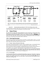
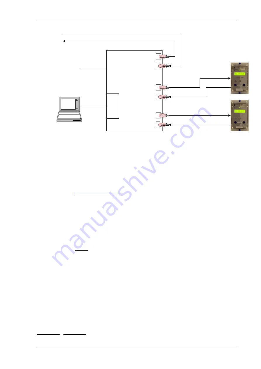
Figure 4.2-4
Communication to Multiple Argus Relays from Control System and Laptop with Sigma 1
and Fibre-optic Star Network
4.3 Introduction – Modbus RTU
(Not available in Argus 4 & Argus 6)
This section describes how to use the Modbus Interface with a compliant control system. For further information
regarding the interface, reference should be made to the Argus Modbus implementation report 434/TIR/14
available on website
www.siemens.com/energy
The same communications interface is used to provide control system connections.
The Argus complies with the physical requirements of Modbus using fibre-optics or an RS485 interface.
4.3.1 Medium
The communicating medium is optical fibre or electrical RS485. The device communicating with the Argus should
have an interface optimised for 62.5/125 µm glass fibre-optics, or RS485 electrical connection.
4.3.1.1
Sigma Fibre-optic to RS232 Converters
See previous section 4.2.2.1.
4.3.2 Recommended cable
Selection of fibre-optic cable is important. Fibres must be terminated with ST
TM
(BFOC/2.5) connectors. The
recommended type is 62.5/125µm glass fibre. Communication distances over 1 km are achievable using this type
of fibre.
The RS485 electrical interface can be connected using 120 ohm screened twisted pair wire i.e. Belden 9841 or
equivalent.
4.3.3 Network Topology
Fibre optical communication networks can be connected singularly or in a star configuration. Modbus does not
support a fibre optic ring configuration.
RS485 electrical connection can be used in a single or multi-drop configuration. The last device must be
terminated correctly.
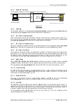
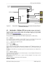
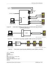
Figure 4.2-1 & Figure 4.2-4 illustrate typical network arrangements.

