7SG11 Argus Technical Reference
©2013 Siemens Protection Devices Limited
P20007 Page 29 of 71
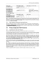
Setting name
Range (
bold
= default)
Units Notes
Gn P/F [E/F] Highset 1Delay
0.00
, 0.01…20.00, 20.5 …100, 101 …
300
sec
Gn P/F [E/F] Highset 2 Dir
Control
OFF
, FWD, REV, TRI
Argus 2 and Argus 6 only.
Gn P/F [E/F] Highset 2 Setting
OFF
, 0.05, 0.1…3.00,
3.5, 4.0…52.5
xIn
Gn P/F [E/F] Highset 2 Delay
0.00
, 0.01…20.00, 20.5 …100, 101 …
300
sec
see note 1 below
Sub-menu:
O/P Relay Config.
Setting name
Range (
bold
= default)
Units Notes
Gn P/F [E/F] Starter
_, 1 for each output contact
(default:
_ _ _ _ _ _ _ _ _ _ _
)
Gn P/F [E/F] Charact.
Gn P/F [E/F] Lowset
Gn P/F [E/F] Highset 1
Gn P/F [E/F] Highset 2
_, 1 for each output relay R1 – R11
(default:
_1_ _ _ _ _ _ _ _ _
)
see note 1 below
default settings - all protections
energise output relay 2
Sub-menu:
Status Config.
Setting name
Range (
bold
= default)
Units Notes
Gn P/F [E/F] Charact. Inhib.
Gn P/F [E/F] Lowset Inhib.
Gn P/F [E/F] Highset 1 Inhib.
Gn P/F [E/F] Highset 2 Inhib.
_, 1 for each status input S1 – S11 and
Vstart
(default
: _ _ _ _ _ _ _ _ _ _
)
Argus 2 type II relays only, each
element can be set to be inhibited
from the voltage element starter.
Note 1. If the directional control is set to tri-state, these settings will be duplicated for forward and reverse
directions. The settings for the forward direction are indicated by an ‘F’ following the group number (e.g.
GnF P/F
Charact.
), while the settings for the reverse direction are indicated by an ‘R’ (e.g.
GnR P/F Charact.
).
Note 2. The above table shows the settings for phase-fault elements, with the text for earth-fault indicated by
square brackets, e.g.
Protection:
Gn P/F Charact. Dir Control
becomes
Protection:
Gn E/F Charact. Dir Control
.
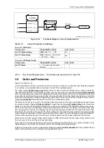
2.3.3 Flashing (Pecking) Fault Protection
Flashing Faults are characterised by a series of short pulses of fault current which are intermittent, if the
IDMT/DTL element characteristic has an instantaneous reset then it may not operate. In order to detect and
operate for such faults the relay has a setting that enables the user to set the
Protection:
Relay Reset Delay
. This
setting modifies the reset-mode of the IDMT/DTL protection algorithm such that after the fault current has
disappeared the current time totals are held. For faults that re-appear within the Relay Reset Delay time the
current~time integration continues from the last value reached. Where the fault current does not reappear within
the Relay Reset Delay time then the integrator will reset to zero and any subsequent fault will start a new
integration of current~time. Thus for flashing faults where the fault current pulses reappear within the set reset
time, up to 60 seconds after the end of the last pulse, the delayed characteristic will operate on the summation of
the fault current~time.
Where auto-reclose is not required after a delay protection trip i.e. sequence = 2I + 1D, then the Relay Reset-
Delay time setting should be set to
60sec
. Where a delay protection trip is to be followed by auto-r delay
protection then this setting may be left at the default value of instantaneous or set to a time which is less than the
reclose delay between consecutive delay protection operations. Setting times as above will provide flashing fault
coverage and still allow grading between relays in series on the system.
If this function is not required the Relay Reset Delay time can be set to ‘
INST’
.
Table 2-12
Flashing Fault Setting
Sub-menu:
Protection
Setting name
Range (
bold
= default)
Units Notes
Gn Relay Reset Delay
INST
, 1,2…60
sec


