7SG11 Argus Technical Reference
©2013 Siemens Protection Devices Limited
P20007 Page 46 of 71
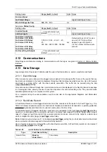
Output Relay Minimum Energise Time
All relay outputs can have their minimum energise time set by the
O/P Relay Config.:
Min O/P Energise Time
.
Status Input Inversion and Delays
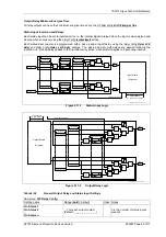
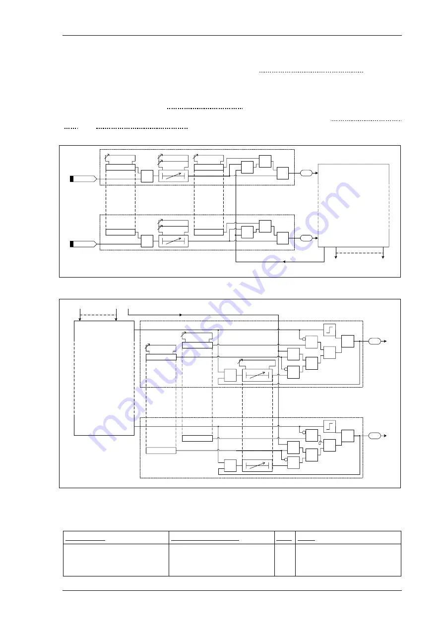
Each status input can be set to inverted action i.e. the internal signal is raised when the input is de-energised and
cleared when energised, using the
Status Config.:
Inverted Inputs
setting.
Each status input can also be programmed with a pick-up and drop-off delay, using the
Status Config.:
Status n P/U
Delay
and
Status Config.:
Status n D/O Delay
settings. The pick-up and drop-off delays are applied following the
inversion, i.e. pick-up delay applies to the input becoming active, while drop-off applies to it becoming inactive.
Event
Status 1
1
Status 1
=1
Inverted Inputs
Status 1 inverted
Status 1 D/O Delay
Status 1 P/U Delay
Latched Inputs
Status 1 latched
S
R
Q
Event
Status
n
1
Status
n
=1
Status
n
inverted
Status
n
D/O Delay
Status
n
P/U Delay
Status
n
latched
S
R
Q
Input Matrix
(Or gates)
Logic signals,
e.g. 'P/F Charact. Inhibit'
P300008 Protection Functions / Input
Reset Flags & Outputs
Figure 2.11-1
Status Input Logic
Event
Relay 1
Min O/P Energise Time
Hand Reset
Relay 1 hand reset
S
R
Q
Output Matrix
(Or gates)
Logic signals,
e.g. 'P/F Charact.'
P300008 Protection Functions / Input
Reset Flags & Outputs
Pulsed Relays
Relay 1 pulsed
&
1
&
&
1
1
Event
Relay
n
Relay
n
hand reset
S
R
Q
Relay
n
pulsed
&
1
&
&
1
1
Figure 2.11-2
Output Relay Logic
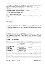
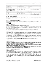
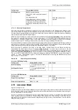
Table 2-24
General Output Relay and Status Input Settings
Sub-menu:
O/P Relay Config.
Setting name
Range (
bold
= default)
Units Notes
Gn Status 1
Gn Status 2
…
Gn Status n
_, 1 for each output contact
(default:
_ _ _ _ _ _ _ _ _ _ _
)
n is the number of status inputs
present


