7SG11 Argus Technical Reference
©2013 Siemens Protection Devices Limited
P20007 Page 47 of 71
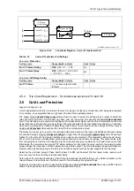
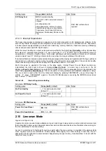
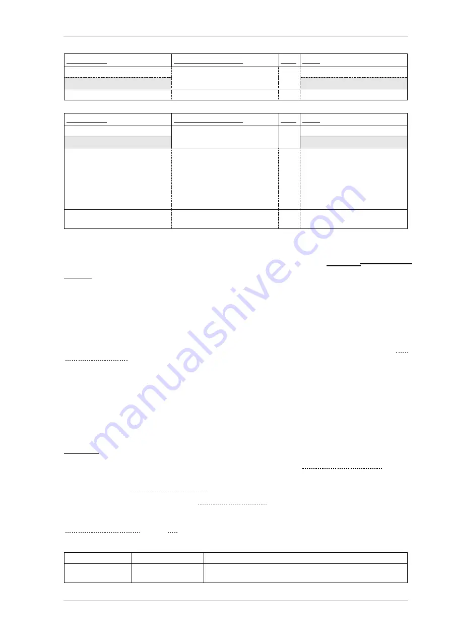
Setting name
Range (
bold
= default)
Units Notes
Gn Hand Reset
Gn Pulsed Relays
Argus 4 and Argus 6 only.
Min O/P Enegerise Time
100
, 150…500
ms
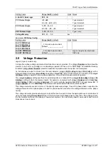
Sub-menu:
Status Config.
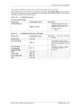
Setting name
Range (
bold
= default)
Units Notes
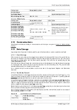
Inverted Inputs
Latched inputs
_, 1 for each status input
(default:
_ _ _ _ _ _ _ _ _
)
Argus 4 and Argus 6 only.
Gn Status 1 P/U Delay
Gn Status 1 D/O Delay
Gn Status 2 P/U Delay
Gn Status 2 D/O Delay
…
Gn Status n P/U Delay
Gn Status n D/O Delay
0.00, 0.01, 0.02…2.0, 2.1…20,
21…
300, 360…3600, 3900…14400d
sec
Default settings of 0.02 for pick-
up and 0.01 for drop-off are
applied to give AC rejection.
n is the number of status inputs
present.
Gn Reset Flag & Outputs
_, 1 for each status input
(default:
_ _ _ _ _ _ _ _ _
)
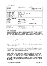
2.12 Communications
All settings and information relating to communications with the Argus, are given in Section 4: Communication
Interface.
2.13 Data Storage
Argus relays store three types of data to assist the user in fault evaluation i.e. events, waveforms and faults.
2.13.1 Event Storage
When an event occurs a date and time tagged entry is added to the storage buffer. Some of the events that can
be stored are indicated in the function diagrams throughout this functional description section. Up to 500 events
are stored in a rolling buffer, with the oldest events overwritten. The buffer can be cleared using the
Data
Storage:
Clear All Events
setting.
All events can be obtained through the communications link and are displayed in the Reydisp Evolution package
in chronological order, allowing the user to see the sequence of events surrounding a trip. They are also made
available spontaneously to a compliant control system.
For a complete listing of events available in each model refer to the appropriate Diagrams and Parameters
document.
2.13.2 Fault Data Record
A Fault Data Record is a time-tagged textual record of the conditions at the instant of a Fault Trigger e.g. Trip,
Table 2-25 shows all possible entries in a fault record. Details are included of all operated or operating protection
elements, magnitudes and directions of currents in each pole at the time of trip.
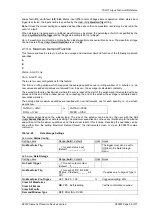
A Fault Data record is triggered when any output relay, as designated in the
Data Storage
Gn Fault Trigger
setting,
operates in combination with any protection element, or a status input mapped to a Fault Trigger output relay is
raised. To trigger a Fault Data record from an external protection device connect its trip output to a status input
which is mapped to a
Data Storage:Gn
Fault Trigger
output relay.
Note.
Unless an output relay is set=1 in the
Data Storage:
Fault Trigger
setting then no fault data record will be stored
when a protection function assigned to that output relay operates.
Up to 5 faults are stored in a rolling buffer, with oldest faults overwritten. All Fault Data records can be cleared if
Data Storage:
Clear All Faults
is set to
YES
.
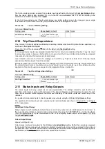
Table 2-25
List of Entries for Fault Data Records
Type
Fault Record Entry
Description
Date & Time
dd/mm/yy
hh:mm:ss.ssss
Time stamp

