7SG11 Argus Technical Reference
©2013 Siemens Protection Devices Limited
P20007 Page 58 of 71
P300005 Application Diagrams / Busbar Dbl Src
Incomer
Fwd
Rev
Rev
Fwd
Rev
Fwd
HS2 Fwd
HS1,
IDMT
Incomer
Rev
Fwd
HS1,
IDMT
Incomer
HS2 Fwd
HS1,
IDMT
HS2
Rev
HS2
Rev
HS2
Fwd
HS2
Fwd
HS2 Fwd
HS1
Inhibits
HS2 Fwd
HS2 Fwd
HS2 Fwd
HS1
Inhibits
HS1,
IDMT
HS1,
IDMT
HS1
Inhibits
HS1
Inhibits
HS1
Inhibits
HS1,
IDMT
HS1,
IDMT
HS1
Inhibits
HS1
Inhibits
HS1
Inhibits
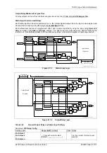
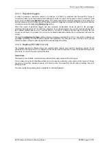
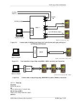
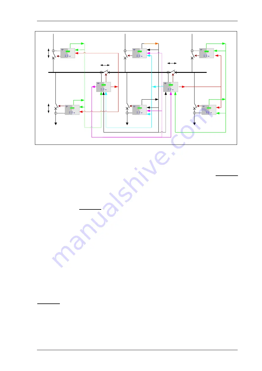
Figure 3.4-3
Busbar Zone Protection with Circuit Breaker Fail Employing Bi-Directional relays. For
use on fully Interconnected Networks with Remote Supply Sources
If bus coupler and bus section circuit breakers are equipped with CTs and suitable VTs are available, then bi-
directional Argus relays can be fitted to those circuits. Suitable steering of blocking and tripping signals can
ensure that in the event of a busbar fault only the minimum plant is disconnected from the system. Figure 3.4-3
shows a typical example of this. If there are no CTs on the bus sections/couplers, a staged tripping logic can still
be established to achieve the same result, although in a little longer time.
3.5
High Impedance Restricted Earth-fault Protection
The SEF/REF element of the Argus can be used to provide high impedance balanced or restricted earth-fault
protection as shown in Figure 3.5-1. The SEF/REF starter output is used to provide an instantaneous trip output
from the relay.
A separate Siemens Protection Devices Limited. Publication is available covering the calculation procedure for
REF protection.
To summarise the calculation:
The relay Stability (operating) Vs voltage is calculated using worst case lead burden to avoid relay operation for
through-fault conditions where one of the CTs may be fully saturated. The required fault setting (primary operate
current) of the protection is chosen; typically, this is between 10 % and 25 % of the protected winding rated
current. The relay setting current is calculated based on the secondary value of the operate current, note,
however, that the summated CT magnetising current @ Vs must be subtracted to obtain the required relay
operate current setting.
Since the relay operate current setting and stability/operating voltage are now known, a value for the series
resistance can now be calculated.
A check is made as to whether a Non-Linear Resistor is required to limit scheme voltage during internal fault
conditions – typically where the calculated voltage is in excess of 2kV.
The required thermal ratings for external circuit components are calculated.
Figure 3.5-2 shows the secondary wiring circuit, including the non-linear resistor, if required.


