7SG11 Argus Technical Reference
©2013 Siemens Protection Devices Limited
P20007 Page 60 of 71
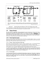
3.6 Circuit Breaker Fail Protection
The Argus relay incorporates a two-stage circuit breaker fail feature. If a designated trip relay operates and the
circuit breaker fails to open, the protection algorithm continues to run for as long as current, above the starter
level or CBF level detector setting, continues to flow and a continuous trip output is given. This combination of
conditions is programmed to start a definite time lag feature designated “CB Fail 1”. This function can be
programmed to energise an output relay when the C.B. fail time delay is completed. At the same time operation of
this timer starts a second time lag feature designated “CB Fail 2” and if the trip outputs already initiated do not
stop the current flow through the relay, another relay can be programmed through the output matrix to trip a
further breaker e.g. a bus section circuit breaker.
Schemes
These timers support schemes as follows:
Single stage CB fail, where all adjacent upstream infeeds are tripped after DTL1 on detection of a CB fail
occurrence.
Two stage CB fail, where stage 1 DTL outputs attempt to re-trip the faulted CB in stage 1 time delay and
when this fails the stage 2 time delayed output trips the relevant adjacent infeeds.
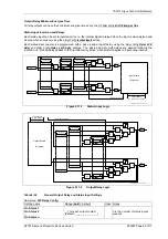
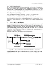
The circuit breaker fail feature can also be used to implement a multi-stage tripping scheme. A typical example of
this is illustrated in Figure 3.4-2.
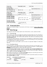
Setting Calculation
The time delay setting applied to the CB fail protection must be in excess of:
the longest CB operate time + relay reset time + a safety margin
Typically, 80 ms + 42 ms + 50 ms = 175ms (approximately)
3.7 Auto-reclose Applications
Argus 4 and Argus 6 only.
Automatic circuit reclosing is extensively applied to overhead line circuits where a high percentage of faults that
occur are of a transient nature and cause no permanent damage to connected plant. The benefits of auto-
reclosing are:
Reduce to a minimum the loss of supply to the customer.
Allows greater automation of the network with relevant cost savings.
Instantaneous fault clearance is possible thereby minimising fault damage.
3.7.1 Reclose Time Setting
The reclose time is defined as the time between the auto-reclose scheme being energised and the operation of
the output contacts that energise the circuit breaker closing circuit. Selection of the optimum time setting is
influenced by the recloser characteristics, the type of load supplied, and the nature of the fault.
The recloser mechanism reset time and closing time (interval between energisation of the mechanism and the
making of the contacts) or the recloser duty cycle make up the minimum reclose time imposed by the recloser.
Where the connected plant consists of a motor circuit, the motor type must be taken into consideration as regards
the requirements of the auto-reclose scheme. Synchronous machines require a reclose time sufficiently long
enough to ensure operation of their undervoltage protection, i.e. should not be reconnected. Whilst for induction
motors the interruption period needs to be short to enable them to coast until reconnection of the supply.
For overhead lines applications the reclose time must be long enough to allow the ionised air to disperse. Factors
that affect the de-ionisation time are the system voltage, cause of the fault, and weather conditions.
3.7.2 Reclaim Time Setting
The reclaim time is defined as the time window following a successful closing operation within which if a fault
occurs the current reclose sequence will continue. After the Reclaim time if a fault occurs a new sequence will
start. Under repetitive fault conditions a long reclaim time in excess of the interval between successive faults may
cause unnecessary lockout and interruption of supply.

