7SG11 Argus Technical Reference
©2013 Siemens Protection Devices Limited
P20007 Page 64 of 71
Section 4: Communication Interface
4.1 Introduction
Argus relays can communicate with controlling systems using either IEC60870-5-103 or MODBUS (Modbus not
available in Argus 4 & Argus 6) communications protocols. The protocol is selectable in the relay settings menu.
4.1.1 Comms Protocol Setting
The relay protocol can be selected from a default setting of IEC60870-5-103 to Modbus RTU (Modbus RTU not
available in Argus 4 & Argus 6) whichever is required. The
Communications Interface:
Comms Protocol
setting should
match that of any communicating device.
4.2 IEC 60870-5-103
Argus relays can communicate with control and automation systems, or with PCs running ReyDisp software, to
provide operational information, post-fault analysis and settings interrogation and editing. This section describes
how to use the IEC 60870-5-103 compliant Informative Communication Interface with a control system or
interrogating computer. Appropriate software within the control system or on the interrogating computer (e.g.
ReyDisp Evolution) is required to access the interface.
This section specifies connection details provided in the Argus relays. For further information regarding the
interface reference should be made to the separate Informative Communications Interface manual (reference
434/TM/5), which covers all Reyrolle products. See website
The same communications interface is used to provide control system connections and for dialogue
communications by the protection engineer. An appropriate IEC 60870-5-103 control system interface will be
required for the former application, while the latter is provided by ReyDisp Evolution software.
4.2.1 Physical Connection
The Argus complies with the physical requirements of IEC 60870-5-103 using fibre-optics however it is possible to
apply more flexible, but non-compliant, settings for connection to PCs etc.
4.2.2 Medium
The communicating medium is optical fibre. The device communicating with the Argus should have a fibre-optic
interface, preferably optimised for 62.5/125 µm glass fibre. If the communicating device, e.g. a PC, has an
RS232C electrical interface, a fibre-optic to RS232 converter is required.
4.2.2.1
Sigma Fibre-optic to RS232 Converters
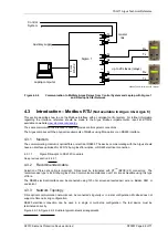
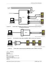
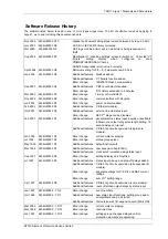
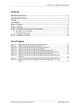
Siemens Protection Devices Limited. can provide a range of fibre-optic to RS232 converter devices:
Sigma 1 – a panel mounting fibre-optic star coupler, for up to 29 slaves. An RS232 port is available at the
front of the device. By default, communication is to the master fibre connections on the rear, however
communication is automatically switched to the front RS232 port when a communicating programme is activated
on it. Each fibre-optic port can be individually selected between ‘Light On’
and ‘Light Off’ (see section 0).
Sigma 3 – a panel mounting fibre-optic to RS232 converter. Two RS232 ports are available, one at the rear
for connection to a modem, and one at the front for connection to a local PC. By default the rear port is active,
however, communication is automatically switched to the front port when a communicating programme is
activated on it. The fibre-optic port can be selected between ‘Light On’
and ‘Light Off’ (see section 0).
Sigma 4 – a loose fibre-optic to RS232 converter.
Full details of the above devices can be found by referring to the website
4.2.3 Recommended cable
Selection of fibre-optic cable is important. Fibres must be terminated with ST
TM
(BFOC/2.5) connectors.
The recommended type is 62.5/125µm glass fibre. Communication distances over 1 km are achievable using this
type of fibre.

