7SG11 Argus Technical Reference
©2013 Siemens Protection Devices Limited
P20007 Page 26 of 71
the relay keypad untouched for an hour the password protection is re-enabled. The Password setting is changed
using the
System Config.:
Change Password
setting. The user set password is also required to be entered for setting
changes or commands performed via the communications link.
Note: if the password is lost/forgotten it can be recovered if the code number shown in the password screen is
communicated to Siemens Protection Devices Limited.
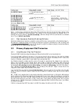
Table 2-10
Password Setting
Sub-menu:
System Config.
Setting name
Range (
bold
= default)
Units Notes
Change Password
ABCDEFGHIJKLMNOPQRSTUV
WXYZ1234567890 -+/
(
NOT ACTIVE
)
4 characters
2.3 Phase-fault and Earth-fault Overcurrent
Argus relays can have up to three phase-fault poles and an earth-fault pole. Each pole has four overcurrent
elements which can be used with the starters in blocking and protection schemes.
Phase-fault and earth-fault poles each have a delayed characteristic plus three instantaneous/definite time delay
elements. In the directionally controlled Argus 2 and Argus 6 relays each phase-fault and earth-fault delay
characteristic, lowset and highset 1 & 2 elements can be independently programmed via their directional control
settings to non-directional, forward directional, reverse directional or bi-directional (tri-state) operation via the
appropriate directional control setting, e.g.
Protection:
P/F Charact. Dir Control
for the phase-fault delay characteristic
element.
The operation start of each element can be inhibited from a mapped status input, set via the
STATUS CONFIG
MENU
, to allow comprehensive blocking schemes to be developed. Furthermore, on Argus 2 relays with type II
directional elements, the voltage element output can be set to raise inhibits.
The current input signals are sampled at a frequency of 1600 Hz (32 times per 50 Hz cycle) giving a flat frequency
response between 47 Hz and 550 Hz, higher harmonics are also included in the r.m.s. calculation. This makes
Argus ideal for applications where true RMS accuracy of measurement and timing must be maintained in the
presence of high harmonic content in the current waveform e.g. protection of lines carrying variable speed motor
loads or for capacitor bank protection.
2.3.1 Delay Characteristic element
The
Protection:
P/F Charact. Setting
enables the current level for the delay characteristic starter to be set. The Delay
characteristic
Protection:
P/F Charact. Setting
can be selected from Inverse Definite Minimum Time (IDMT)
characteristic type Normal Inverse (NI) (IEC type A), Very Inverse (VI) (IEC type B), Extremely Inverse (EI) (IEC
type C) and Long Time Inverse (LTI), or alternatively a Definite Time Lag (DTL) can be chosen. The time
multiplier to be applied to the delay characteristic curve is set using the
Protection:
P/F Charact. Time Mult
setting; if
DTL has been selected this setting is replaced by the
Protection
:P/F Charact. Delay
setting.
Each phase has an independent current-timing element and the algorithms integrate accurately for developing
faults where current magnitude in each pole varies with time. Outputs are programmed using the ‘
O/P Relay
Config.:
P/F Starter
‘ and ‘
O/P Relay Config.:
P/F Charact.
‘ settings for starter pick-up and delayed trip respectively.


