7SG11 Argus Technical Reference
©2013 Siemens Protection Devices Limited
P20007 Page 32 of 71
P300008 Protection Functions / CBF
*see note 1
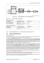
Note 1:- EN, Enable input is edge triggered and level active.
IF CBF is applied then P/F & E/F & SEF must each have an
I
CBF
current setting.
IF any CBF Current Setting = OFF (Zero) then output = 1 when enabled.
Enable/Output is Reset when all currents are OFF (Zero) or all are below setting.
P/F CBF Current Setting
E/F CBF Current Setting
SEF CBF Current Setting
I
ph
I
ef
I
sef
CB Fail Time Delay 1
CB Fail 1
CB Fail Time Delay 2
CB Fail 2
Event
Event
Circuit breaker fail 1
Circuit breaker fail 2
Fault Trigger
Output
relay
Status Input Y
Any Protection Element
ENABLE
1
EN
Figure 2.5-1
Functional Diagram – Circuit Breaker Fail
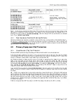
Table 2-14
Circuit Breaker Fail Settings
Sub-menu:
Protection
Setting name
Range (
bold
= default)
Units Notes
Gn P/F CB Fail Setting
OFF,
0.05,
0.1 … 1.00
xIn
Gn E/F CB Fail Setting
OFF,
0.05
,
0.1 … 1.00
xIn
Gn SEF CB Fail Setting
OFF,
0.005 … 0.96
xIn
Gn CB Fail Time Delay 1
Gn CB Fail Time Delay 2
OFF,
0.00, 0.01…20.00, 20.5
…100, 101 … 300 s
sec
Sub-menu:
O/P Relay Config.
Setting name
Range (
bold
= default)
Units Notes
Gn CB Fail 1
Gn CB Fail 2
_, 1 for each output contact
(default:
_ _ _ _ _ _ _ _ _ _ _
)
2.5.2 Close Fail
Argus 4 and Argus 6 only
Circuit breaker close operation is also monitored. The relay checks the status of the CB at the end of each close
pulse. If the CB has not closed then the relay locks out due to CB close fail, and any sequence is terminated.
2.5.3 Current Transformer Failure
The current flowing from each of the Phase Current Transformers is monitored. If one or two of the three input
currents falls below the CT Supervision current setting for more than the CT Failure time delay then CT Failure is
raised. If all three input currents fall below the setting CT Failure is not raised.


