7SG11 Argus Technical Reference
©2013 Siemens Protection Devices Limited
P20007 Page 33 of 71
P300008 Protection Functions / CTF
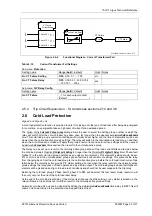
CT Failure Time Delay
CT Failure
Event
CT Failure
CT Failure
Current Setting
I
A
I
B
I
C
1 out of 3 < I
CTF
2 out of 3 < I
CTF
3 out of 3 = no-op
Figure 2.5-2
Functional Diagram – Current Transformer Fail
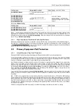
Table 2-15
Current Transformer Fail Settings
Sub-menu:
Protection
Setting name
Range (
bold
= default)
Units Notes
Gn CT Failure Setting
OFF,
0.05,
0.1 … 1.00
xIn
Gn CT Failure Delay
OFF,
0.00, 0.01…20.00, 20.5
…100, 101 … 300 s
sec
Sub-menu:
O/P Relay Config.
Setting name
Range (
bold
= default)
Units Notes
Gn CT Failure
_, 1 for each output contact
(default:
_ _ _ _ _ _ _ _ _ _ _
)
2.5.4
Trip Circuit Supervision - for details see sections 2.10 and 3.8
2.6 Cold Load Protection
Argus 4 and Argus 6 only
A cold load protection function is provided to cater for closing onto the type of load that, after being de-energised
for some time, on energisation takes a high level of current for an extended period.
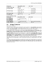
The
System Config.:
Cold Load Pickup Group
setting allows the user to select the setting group number to which the
relay will switch after the circuit breaker has been open for longer than the user-set
Auto-reclose:
Cold Load Enable
time. This cold load group’s overcurrent settings will normally be set higher and the time characteristics will be set
slower than the normally-active group’s settings. The relay will switch to the nominated cold load group n and then
when the circuit breaker is closed will apply that group’s overcurrent and auto-reclose settings until the user-set
Autoreclose:
Cold Load Reset
time expires, then revert to the normally-active group.
The Relay can be set up to revert to the normally active group sooner if the load current falls and remains below
the cold load group’s
Protection:
P/F Highset 2 Setting
for longer than the
Protection:
P/F Highset 2 Delay
timer. Phase-fault
highset 2 in the set cold load group operates as an under-current element. This element’s setting should be set,
5% or more, below the normally-active group’s phase-fault overcurrent element settings. This prevents the relay
from changing back, from the cold load group to the normally active group, before the cold load inrush current has
fallen below the normally active group’s P/F starter settings, so that when the relay reverts to the normally-active
group settings the relay does not then operate and give a trip output. The cold load group’s phase-fault highset 2
element will be picked up during cold load inrush conditions and should not be user mapped to the trip relay.
Selecting the cold load group’s Phase Fault highset 2 to
OFF
will de-select this fast revert mode, reversion will
then only occur at the end of the cold load reset delay.
At the end of the cold load reset delay, if the current is still above the HS2 setting, or any starter is picked up, the
relay will issue a trip and lockout. It will then revert to the normally-active group settings.
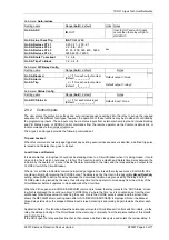
Automatic cold load pick-up can be disabled by setting the
Auto-reclose:
Cold Load Enable
time delay to
OFF
. This still
allows Cold Load Group n to be selected via a mapped Status Input.


