7SG14 Duobias-M-200 Commissioning
1 Introduction
These commissioning recommendations apply to the testing, putting into service and subsequent maintenance of
Duobias-M 200 (DU3-xxx
)
series of numerical protection relays. This range of relays is built on the
Modular ll
hardware platform.
This range of relays can provide differential protection to two and three winding power transformers and other
plant items such as busbars, motors and reactors. Relay models are available for connection of two to five sets
(terminals) of CT’s. VT’s may also be connected to the relay if optional functions are required.
A separate technical manual is available for
Modular l
(DU2-XXX) Duobias M. The type of relay can be easily
checked as
Modular ll
relays have two pairs (Tx&Rx) of rear mounted fibre ports and Modular I relay have only
one pair.
The relay can be used to protect other plant items such as reactors, busbars and motors.
A software program called Reydisp Evolution is available for download from the www.reyrolle-protection.com
website. This allows access to settings, waveform records and event records via relay communications with an
IBM PC compatible computer.
Before starting the test procedures all protection settings and schemes showing the D.C. status input and output
relay configuration must be available.
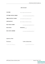
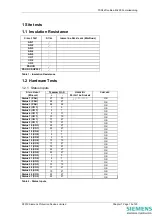
It is recommended use is made of the Test Result Tables provided so that a comprehensive record of the
protection settings, as commissioned, is available for future reference.
2 Safety
The commissioning and maintenance of this equipment should only be carried out by skilled personnel trained in
protective relay testing and capable of observing all the Safety Precautions and Regulations appropriate to this
type of equipment and also the associated primary plant in substations and power stations.
Ensure that all test equipment and leads have been correctly maintained and are in good condition. It is
recommended that all power supplies to test equipment be connected via a Residual Current Device (RCD) which
should be located as close to the supply source as possible.
The choice of test instrument and test leads must be appropriate to the application. Fused instrument leads
should be used when measurements of power sources are involved, since the selection of an inappropriate range
on a multi-range instrument could lead to a dangerous flashover. Fused test leads should not be used where the
measurement of a current transformer (CT) secondary current is involved, the failure or blowing of an instrument
fuse or the operation of an instrument cut-out could cause the secondary winding of the CT to become an open
circuit.
Open circuit secondary windings on energised current transformers are a hazard that can produce high voltages
dangerous to personnel and damaging to equipment, test procedures must be devised so as to eliminate this risk.
3 Sequence of Tests
If other substation equipment is to be tested at the same time as the Duobias-M, then such testing must be co-
ordinated to avoid danger to personnel and equipment.
When cabling and wiring is complete, a comprehensive check of all terminations for tightness and compliance
with the approved diagrams must be carried out. This can then be followed by the insulation resistance tests,
which if satisfactory allows the wiring to be energised by either the appropriate supply or test supplies. When
injection tests are completed satisfactorily, all remaining systems can be functionally tested before the primary
circuit is energised. Some circuits may require further tests, e.g. synchronizing before being put on load.
4 Test equipment required
Various test sets designed for protection testing can be used to test the relay providing these allow injection the
current sources with a sinusoidal waveform. If the CT secondary rating is 5A the bias characteristic may be tested
single phase to allow test set amplifiers to be paralleled.
©2010 Siemens Protection Devices Limited
Chapter 7 Page 4 of 20


