7SG14 Duobias-M-200 Commissioning
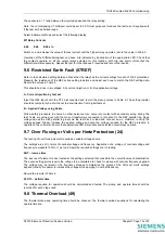
Time to trip
⎭
⎬
⎫
⎩
⎨
⎧
−
×
τ
=
2
2
2
)
I
(
I
I
ln
θ
t(mins)
where,
t – operate time in minutes
I - applied current in terms of x In
I
Θ
- thermal pick-up setting x In
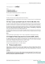
The steady state % thermal capacity used can be calculated from:
100
)
I
(
I
2
2
×
⎟⎟
⎠
⎞
⎜⎜
⎝
⎛
=
θ
used
capacity
thermal
%
The pickup value and accuracy of timing should be within 5% of setting.
A typical operate time with 2 x pickup applied and a time constant of 1 minute would result in a calculated operate
time of 17.26 seconds.
9.9 Over Current and Earth Fault (51, 51N, 50, 50N, 50G, 51G)
The pickup and timing should be tested for each element. Earth Fault elements may be measured (51N) from a
neutral CT’s or derived for line CT inputs (51G). This will affect where the injection must be made to allow testing.
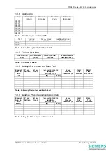
The pickup level, operate and reset time should be recorded in Table 10. The ANSI overcurrent elements also
have inverse reset curves that may be tested. The IEC curves may have a DTL reset applied. The reset delays
are used to ensure grading between differing types of relays, if “pecking” or intermittent type of faults earth
occurs. These are quite common on power cables particularly XLPE.
The 50G/51G elements require current to be applied to the phase inputs as the earth fault current is derived from
the residual (sum) of the three phase current inputs. The 50N/51N elements are measured directly from the single
Aux I/P input.
NOTE
All (51) elements have a minimum pickup of 1.05 xI
s
, all (50) elements have a minimum pickup of 1.00 xI
s
.
9.10 Negative Phase Sequence Over Current (46DTL, 46ITL)
The negative sequence current is measured from the phase inputs. Pure negative phase sequence current can
be injected by swapping the phase relationship of two of the phase currents. This can be achieved by swapping
over two leads or changing the set phase angle of two of the three currents.
The NPS current then equals the value of the phase current injected.
The pickup level and operate times can be recorded in Table 13.
10 Primary injection tests
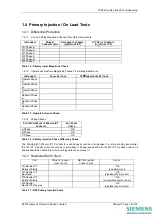
Primary injection is recommended to prove the relay connections, CT polarity and settings before putting the
protection scheme into service. To prove the connections of REF protection a primary injection must be done. The
differential protection can also be proven using load current if a risk of trip is permitted and step 10.1 is then not
necessary.
WARNING!
It is important before carrying out any primary injection to ensure appropriate CTs are shorted to avoid
operation of mesh corner or busbar type unit protection. If the injected primary current is large enough,
the bus zones protection may trip out unnecessarily!
©2010 Siemens Protection Devices Limited
Chapter 7 Page 11 of 20


