7SG14 Duobias-M-200 Commissioning
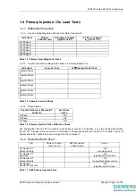
1.4 Primary Injection / On Load Tests
1.4.1 Differential Protection
1.4.1.1 Line And Relay Magnitude Checks From Relay Instruments
I
NSTRUMENT
P
RIMARY
C
URRENTS
(kA)
S
ECONDARY
C
URRENTS
(A)
[B
EFORE
ICT]
ICT
R
ELAY
C
URRENTS
(
X
I
N
)
[A
FTER
ICT]
W1 Phase A
W1 Phase B
W1 Phase C
W2 Phase A
W2 Phase B
W2 Phase C
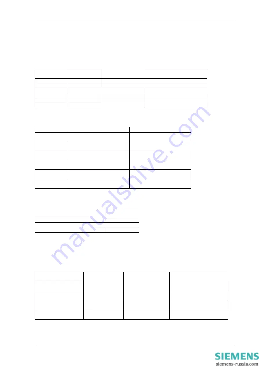
Table 14 - Primary Inject Magnitude Check
1.4.1.2 Operate and Restrain Magnitude Checks From Relay Instruments
I
NSTRUMENT
A
CUAL
S
ETTINGS
180
°
U
NBALANCED
S
ETTINGS
Operate Phase
A
Operate Phase
B
Operate Phase
C
Restrain Phase
A
Restrain Phase
B
Restrain Phase
C
Table 15 - Operate Currents Check
1.4.1.3 Phase Checks
P
HASE
D
IFFERENCE OF
W
INDING
ICT
C
URRENTS
A
NTI
P
HASE
C
HECK
A Phase
OK
B Phase
OK
C Phase
OK
Table 16 - Primary Injection Phase Difference Check
The Winding (W1,W2 etc) ICT Currents for each phase should be in anti-phase. For a two winding transformer
the W1 ICT A phase current should be in anti-phase (180 degrees apart) with the W2 ICT A phase current. All
phases should be checked to ensure wiring errors are not present.
1.4.2 Restricted Earth Fault
T
EST
P
RIMARY
C
URRENT
I
NJECTED
(A)
REF
S
ECONDARY
C
URRENT
(
M
A)
C
HECK
W1 Neutral CT
Normal Polarity
OK
(no spill current)
W1 Neutral CT
Reversed
OK
(significant spill current)
W2 Neutral CT
Normal Polarity
OK
(no significant spill current)
W2 Neutral
Neutral CT Reverse
OK
(significant spill current)
Table 17 - REF Primary Injection Tests
©2010 Siemens Protection Devices Limited
Chapter 7 Page 19 of 20

