7SG14 Duobias-M-200 Commissioning
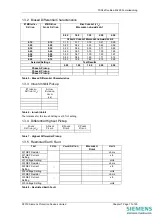
If voltage inputs are provided on the relay, apply nominal voltage to the relay and record the results displayed on
the relay Instruments display (Voltage Meters). The voltage input terminals may be identified by viewing the label
on the rear of the fascia door. These are normally terminal 11 and 12 of one of the analogue modules.
Record the Results in Table 1 below.
If the relay measurement is within tolerance proceed to 9.2 below. If any of the measurements are outside the
stated tolerance (±5%) the relay must be sent back to the Quality Assurance Department for investigation.
Otherwise advice can be obtained from Customer Services Department (++00 44 (0)191 401 5190).
9.3 Checking the Bias Characteristic (87BD)
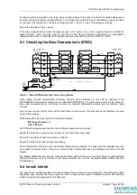
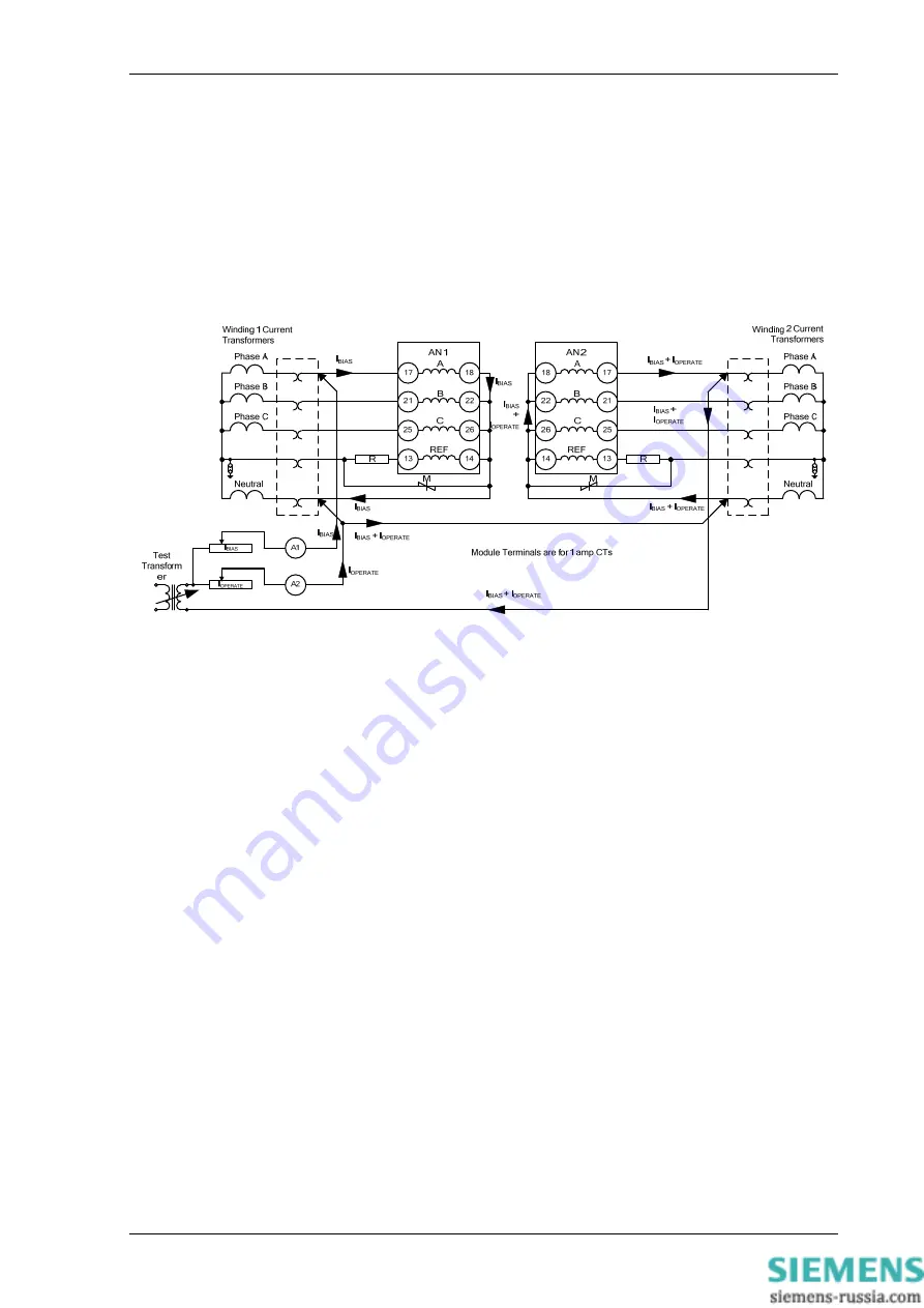
Figure 1 - Biased Differential Test Circuit using Variacs
When testing the bias characteristic, the Relay Currents can be displayed on the LCD by changing to the
INSTRUMENTS mode and scrolling down to [ BIAS DIFF METERS ]. The Instruments to view to help check the
relay bias characteristics are the Relay Currents, the Operate (differential) currents and the Restrain (bias)
currents.
Inject nominal current into W1 Red and W2 Red Phase current inputs. If the test set has the facilities it can also
be done three-phase.
While testing the bias slope, select the Instrument display: -
W1 Relay Currents x I
N
0.00 0.00 0.00
The Differential Operate and Restrain Current Meters should also be checked.
Repeat the tests with increasing bias currents up to 2.5 times the relay rating.
Record the results and check for accuracy in Table 5
Repeat the tests for the other phases if necessary.
Check that the Bias Currents on the Instruments Display are as expected. The upper bias characteristic may also
be checked if required. Some of the more common bias characteristics used are displayed in Section 2 of this
manual.
The Biased Differential may also be conveniently tested using an Omicron Test Unit. Please contact Siemens
Protection Devices Ltd for an Omicron test object template (.occ) for the Duobias-M Biased Differential Test
Characteristics.
9.4 Inrush Inhibit
The relay has an anti-aliasing filter that does attenuate the even harmonic content slightly. The attenuation differs
depending upon whether the relay is used on a 50 or 60Hz power system. Software revisions R15 onwards
include an automatic adjustment for this filter loss.
©2010 Siemens Protection Devices Limited
Chapter 7 Page 8 of 20


