background image

7SG14 Duobias-M-200 Commissioning 


The relay has a built feature to avoid a false operation when energising a transformer. This uses the presence of 
even harmonic in the operate signals to distinguish between an inrush and an internal fault. Three different 
methods are included in the relay. 

The test method will depend upon the Inrush Restraint Method selected. As previously mentioned the SUM 
method has an advantage over the CROSS method in terms of operating speed if an internal fault occurs on 
energising the transformer.    

Only the Inrush Restraint method selected need be tested. 

Sum  - Restraint Method 

This method uses one Inrush Sum some with which to compare the operate current in each phase. The square 
roots of the even harmonic content in each phase differential current is summed and then divided by the Inrush 
Setting to arrive at an overall threshold.  

Cross – Inhibit Method  

The magnetising inrush restraint feature can be checked by injecting the relay with 2

nd

 harmonic current into one 

set of inputs while fundamental is injected into another set of inputs. If possible the test should be done three 
phase as all phases are blocked if one phase exceeds the Inrush Inhibit Setting.  

Check the 

87 Inrush Inhibit

 setting is set to [Enabled]. 

Inject W1 inputs with a balanced three phase current of nominal amplitude and frequency. This will operate all 
three phases of the biased differential function. The 87BD and phase LED’s will be lit. 

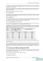
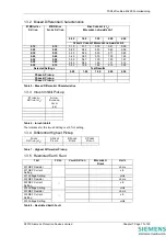
Inject about 5% of nominal 2

nd

 harmonic current into W2 inputs. Slowly raise the 2

nd

 Harmonic Current until the 

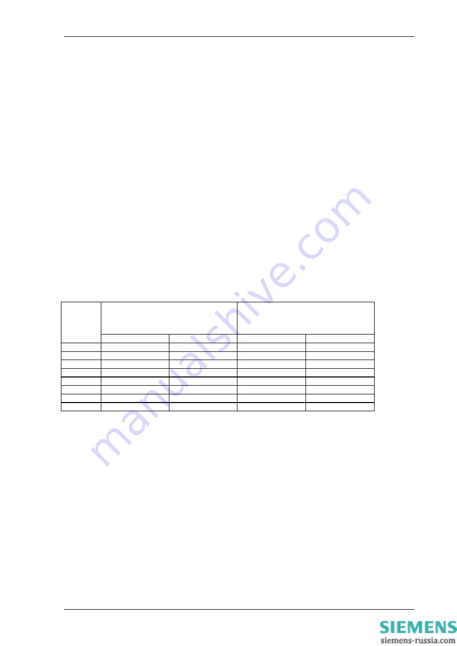
biased differential resets. The approximate levels of 2

nd

 harmonic to block operation are set out in the table below. 

Digital Test sets such a Omicron 256-6 use a ratio injection to test the relay inhibit, the Duobias M does not work 
like this as its setting is a percentage of the operate current.  

2

ND


H

ARMONIC 

C

URRENT INTO 

W2

 REQUIRED 

TO BLOCK 

87BD

 FOR NOMINAL 

FUNDAMENTAL CURRENT INJECTION OF 

W1


INPUTS


S

ETTING AT RECOMMENDED TEST POINT IN 

TERMS OF 

2

ND  

/

 OPERATE


I

NRUSH 

S

ETTING


(

FRACTION 

OF 

I

OP

50 Hz Relay(x I

n

60 Hz Relay(x I

n

50Hz Relay(x I

n

60Hz Relay(x I

n

0.10 0.108 

0.120 0.100 0.132 

0.12 0.128 

0.144 0.121 0.159 

0.14 0.150 

0.168 0.141 0.186 

0.16 0.172 

0.192 0.161 0.213 

0.18 0.194 

0.219 0.181 0.241 

0.20 0.216 

0.245 0.200 0.268 

0.22 0.239 

0.268 0.220 0.296 

0.24 0.262 

0.293 0.240 0.325 

The relay will filter out some of the second harmonic content in currents due to the anti-aliasing filter roll off. 

The filter response attenuates the 2

nd

 (100Hz) harmonic current by approximately x 0.94 for a 50Hz Relay, and by 

x 0.84 for a 60Hz relay.  

The root mean square value of operate current must be calculated, as this is what is used to set the Inrush Inhibit 
level. Typically digital test sets such as the Omicron uses 2

nd

 Harmonic / Fundamental to check the relay 

accuracy. However the relay uses the percentage of second harmonic to the root mean square of operate current. 
As the operate current includes the injected 2

nd

 harmonic as well as the fundamental this must be taken into 

account. 

9.5  Checking the Differential Highset (87HS) 

Connect the test current source to relay or test plug. The test can be done single phase or three phase. This tests 
requires the injection of current in excess of the relay rating, so ensure that the duration of the test does not 
exceed the relay overload withstand rating. 

Use the LCD display to check that the LV input settings are as follows: 

LV Interposing CT Multiplier 1.00 

LV Interposing CT Connection Yy0 

©2010 Siemens Protection Devices Limited  


 Chapter 7 Page 9 of 20 

Summary of Contents for 7SG14 Duobias-M-200

Page 1: ...cument unless Siemens Protection Devices Limited consent While the information and guidance given in this document is believed to be correct no liability shall be accepted for any loss or damage caused by any error or omission whether such error or omission is the result of negligence or any other cause Any and all such liability is disclaimed 2010 Siemens Protection Devices Limited 7SG14 Duobias ...

Page 2: ...Earth Fault 51 51N 50 50N 50G 51G 11 9 10 Negative Phase Sequence Over Current 46DTL 46ITL 11 10 PRIMARY INJECTION TESTS 11 10 1 Biased Differential Protection 12 10 2 Restricted Earth Fault 12 11 TESTS USING LOAD CURRENTS 12 12 PUTTING INTO SERVICE 13 13 SITE TEST SHEET 13 1 SITE TESTS 15 1 1 Insulation Resistance 15 1 2 Hardware Tests 15 1 2 1 Status Inputs 15 1 2 2 Output Relays 16 1 3 Secondar...

Page 3: ...ntial Characteristics 17 Table 6 Inrush Inhibit 17 Table 7 Highset Differential Pickup 17 Table 8 Restricted Earth Fault 17 Table 9 Over Fluxing Inverse Curve 24IT 18 Table 10 Over Fluxing Dual Definite Time 24DT 18 Table 11 Thermal Overload 18 Table 12 Backup Overcurrent and Earth Fault 18 Table 13 Negative Phase Sequence Over current 18 Table 14 Primary Inject Magnitude Check 19 Table 15 Operate...

Page 4: ...are in good condition It is recommended that all power supplies to test equipment be connected via a Residual Current Device RCD which should be located as close to the supply source as possible The choice of test instrument and test leads must be appropriate to the application Fused instrument leads should be used when measurements of power sources are involved since the selection of an inappropr...

Page 5: ... therefore the relay itself does not requires a pressure test The external wiring must still be tested for any insulation breaks Before commencing a visual inspection of the wiring take the following precautions Isolate the auxiliary supplies Remove the trip and inter trip links Check that the relay wiring is complete and that all terminal connections are tight and remove the earth links before co...

Page 6: ...a 25pin RS232C type communications port on the front of the fascia This should be connected to a laptop using a 25 to 9 pin RS232 cable Alternatively a USB connection to the laptop may be used but this may require some Reydisp Configuration changes Reydisp Evolution should be installed on the laptop and this should run on any MS Windows operating system To use the relay communications port the Com...

Page 7: ... set to use is an Omicron Type CMC256 or CMC156 plus CMA156 Automatic test software can be provided to allow input of settings and automatic testing and reporting The Omicron set should be connected in accordance with the manufacturer s instructions The following settings must be selected on relay to avoid any confusion during testing The initial and bias slopes settings should be set to the chose...

Page 8: ...rrents Inject nominal current into W1 Red and W2 Red Phase current inputs If the test set has the facilities it can also be done three phase While testing the bias slope select the Instrument display W1 Relay Currents x IN 0 00 0 00 0 00 The Differential Operate and Restrain Current Meters should also be checked Repeat the tests with increasing bias currents up to 2 5 times the relay rating Record...

Page 9: ...Test sets such a Omicron 256 6 use a ratio injection to test the relay inhibit the Duobias M does not work like this as its setting is a percentage of the operate current 2ND HARMONIC CURRENT INTO W2 REQUIRED TO BLOCK 87BD FOR NOMINAL FUNDAMENTAL CURRENT INJECTION OF W1 INPUTS SETTING AT RECOMMENDED TEST POINT IN TERMS OF 2ND OPERATE INRUSH SETTING FRACTION OF IOP 50 Hz Relay x In 60 Hz Relay x In...

Page 10: ...personnel can come into contact with secondary wiring during this test Tests are carried out with the current transformers connected in idle shunt to the REF parallel leg Apply voltage across the REF parallel leg input via the test block or lead and connect an a c voltmeter to verify the voltage applied Slowly increase the applied voltage and note the voltage required for the REF protection to ope...

Page 11: ...ent is derived from the residual sum of the three phase current inputs The 50N 51N elements are measured directly from the single Aux I P input NOTE All 51 elements have a minimum pickup of 1 05 xIs all 50 elements have a minimum pickup of 1 00 xIs 9 10 Negative Phase Sequence Over Current 46DTL 46ITL The negative sequence current is measured from the phase inputs Pure negative phase sequence curr...

Page 12: ... a definite result to be established Place a temporary short across the setting resistor to allow the secondary current to be measured Insert the test block with necessary shorts across from CT to relay side Inject primary current sufficient to allow measurement Measure and record the REF spill current displayed by the appropriate relay Instrument This spill current should be very small e g a few ...

Page 13: ...B C currents are negligible 12 Putting into service Ensure that The trip supply is connected Press the CANCEL button several times on the front of the relay to move back to the top of the menu structure Press the TEST RESET pushbutton None of the RED LEDs should be illuminated Check the Protection Healthy GREEN LED has continuous illumination Ensure that all earth links trip links and inter trip l...

Page 14: ...NS CONTRACT NUMBER ______________________________ SITE CIRCUIT REF ______________________________ RELAY SERIAL NUMBER ______________________________ RELAY MODEL DUOBIAS M 2______ RELAY ARTICLE NUMBER ______________________________ Signatures and Date Test Engineer Customers Representative 2010 Siemens Protection Devices Limited Chapter 7 Page 14 of 20 ...

Page 15: ...llz z z OK Status 2 PSU 25 27 OK Status 3 PSU 26 28 OK Status 4 I O 1 1 3 OK Status 5 I O 1 5 7 OK Status 6 I O 1 9 11 OK Status 7 I O 1 13 15 OK Status 8 I O 1 17 21 OK Status 9 I O 1 19 21 OK Status 10 I O 1 23 27 OK Status 11 I O 1 25 27 OK Status 12 I O 2 1 3 OK Status 13 I O 2 5 7 OK Status 14 I O 2 9 11 OK Status 15 I O 2 13 15 OK Status 16 I O 2 17 21 OK Status 17 I O 2 19 21 OK Status 18 I...

Page 16: ...elay 19 I O 2 N O 20 22 OK Relay 20 I O 2 N O 24 28 OK Relay 21 I O 2 N O 26 28 OK Relay 22 I O 3 N O 2 4 OK Relay 23 I O 3 N O 6 8 OK Relay 24 I O 3 N O 10 12 OK Relay 25 I O 3 N O 14 16 OK Relay 26 I O 3 N O 18 22 OK Relay 27 I O 3 N O 20 22 OK Relay 28 I O 3 N O 24 28 OK Relay 29 I O 2 N O 26 28 OK Table 3 Output Relay Contacts 1 3 Secondary Injection 1 3 1 Accuracy of Measurement TEST AVAILABL...

Page 17: ...se B Pickup Phase C Pickup Table 5 Biased Differential Characteristics 1 3 3 Inrush Inhibit Pickup 87 INRUSH SETTING XID ACTUAL BLOCKING LEVEL XID Table 6 Inrush Inhibit The tolerance for the Inrush Setting is 10 of setting 1 3 4 Differential Highset Pickup PHASE SETTING XIN A PHASE PICKUP B PHASE PICKUP C PHASE PICKUP Table 7 Highset Differential Pickup 1 3 5 Restricted Earth Fault TEST FITTED VA...

Page 18: ...ERATE TIME SECONDS Table 11 Thermal Overload 1 3 8 Backup Over current and Earth Fault CALCULATED OPERATE TIME S AT MULTIPLE OF PU ELEMENT ANSI NO E G 51N PICKUP SETTING ACTUAL PICKUP s x PU ACTUAL OPERATE TIME DELAY S RESET TIME APPLIED RESET TIME RECORDED Table 12 Backup Overcurrent and Earth Fault 1 3 9 Negative Phase Sequence Over current CALCULATED OPERATE TIME S AT MULTIPLE OF PU ELEMENT ANS...

Page 19: ...cks PHASE DIFFERENCE OF WINDING ICT CURRENTS ANTI PHASE CHECK A Phase OK B Phase OK C Phase OK Table 16 Primary Injection Phase Difference Check The Winding W1 W2 etc ICT Currents for each phase should be in anti phase For a two winding transformer the W1 ICT A phase current should be in anti phase 180 degrees apart with the W2 ICT A phase current All phases should be checked to ensure wiring erro...

Page 20: ...icate for the operation of each device OK Protection Healthy Alarm Local and Remote indication and alarm confirmed OK Table 18 Trip Alarm and Indication Test 1 6 Communication TEST ACTION RESULT Local Relay Port Download Settings Confirmed OK Saved Settings File Record the name of the As Installed Settings File s and storage location Remote Relay Access if used Relay Access Confirmed OK Relay Pass...

Reviews: