background image

7SR105 Rho and 7SR17 Rho Applications Guide 


©2018 Siemens Protection Devices 


Chapter 7 Page 10 of 31 


Gn49 Capacity Alarm Setting 

This setting is expressed as a percentage of the thermal state. It is settable from 50 to 100% of the set capacity 

and gives an alarm output if its setting is exceeded. Typically this would be set to 95% to indicate that a potential 

trip condition exists and that the system should be scrutinised for abnormalities. 
 

Gn 49 Load Alarm 

An alarm is provided to indicate load currents above a user set value. High levels of load current may be 

indicative of bearing wear e.g. due to excessive vibration or loss of lubrication.  The supply to the motor can be 

removed before further damage occurs.  
The alarm level is set as a multiple of the thermal overload setting. The range is 0.5 to 1.0 x Itheta Thermal 

Overload and a measured current above the set value will initiate the alarm if set. 


Thermal Restart Inhibit 

This feature is used to prevent motor starting if there is insufficient thermal capacity to satisfactorily complete the 

start operation. This can be initially set to 50% in the absence of further information. 
During commissioning, before starting the protected motor, check the thermal state at the motor by accessing the 

“Thermal Capacity Used” meter and note the value. The motor should then be started with its normal load and, 

when up to speed the “Thermal Capacity Used” value can be re-checked. The difference between these two 

values indicates the magnitude of thermal capacity used to start. This amount must always be available before a 

restart is permitted. For safety, this figure should be multiplied by 1.25. For example, if 20% of capacity is used 

during starting, then 20% x 1.25 = 25%, and the Thermal Restart Inhibit setting should be 75%. 
Alternatively auto-setting can be selected. 

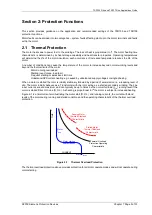
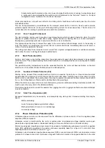
2.1.2  Stall Protection (14) 

TIME

CURRENT

Running Motor 

Thermal Withstand

Stalled Motor 

Thermal Withstand

Thermal Overload

Protection

Motor I

START

Motor

I

RUN

Motor starting 

characteristic


Figure 2-5    Thermal Overload Protection 

The motor will stall when the load torque exceeds the breakdown torque. The motor will draw a stall current equal 

to or approaching locked rotor current. The thermal overload protection may provide protection against stalling 

during running and starting, however,  where this is not possible then the  additional  dedicated stall protection 

functions can be used. Quick motor shut down can reduce thermal damage as well as damage to gears, bearings 

and other drive-train components.  
Stalling may occur during running or may be a failure to accelerate during starting e.g. 

  Excess shaft load prior to motor start-up (e.g. failure to open the pump’s discharge gate) 

  Sudden change of increased shaft load torque during normal operation (e.g. bearing failures) 


Summary of Contents for 7SR105 Rho

Page 1: ...Answers for energy 7SR105 Rho User Manual Motor Protection Relay Reyrolle Protection Devices ...

Page 2: ...Siemens Protection Devices 2 ...

Page 3: ...model or article be reproduced from this document unless Siemens Protection Devices Limited consent While the information and guidance given in this document is believed to be correct no liability shall be accepted for any loss or damage caused by any error or omission whether such error or omission is the result of negligence or any other cause Any and all such liability is disclaimed 2018 Siemen...

Page 4: ...d consent While the information and guidance given in this document is believed to be correct no liability shall be accepted for any loss or damage caused by any error or omission whether such error or omission is the result of negligence or any other cause Any and all such liability is disclaimed 2018 Siemens Protection Devices 7SR105 Rho Description of Operation Document Release History This doc...

Page 5: ...9 2 12 Self Monitoring 20 2 12 1 Protection Healthy Defective 21 Section 3 Protection Functions 22 3 1 Thermal Protection 22 3 1 1 Thermal Protection Overload 49 24 3 1 2 Thermal Protection Stall Protection 14 27 3 1 3 Thermal Protection Start Protection 48 66 28 3 1 4 Thermal Protection Phase Unbalance 46 30 3 2 Current Protection Undercurrent 37 33 3 3 Current Protection Phase Overcurrent 50 51 ...

Page 6: ... Ports 49 6 2 CB Maintenance 52 6 2 1 Output Matrix Test 52 6 2 2 CB Counters 52 6 2 3 I 2 t CB Wear 52 6 3 Data Storage 53 6 3 1 General 53 6 3 2 Demand 53 6 3 3 Event Records 53 6 3 4 Waveform Records 53 6 3 5 Fault Records 54 6 3 6 Disk Activity Warning 54 6 4 Metering 54 6 5 Operating Mode 55 6 6 Control Mode 55 6 7 Real Time Clock 56 6 7 1 Time Synchronisation Data Communication Interface 56 ...

Page 7: ...3 10 Logic Diagram Undercurrent Detector 37 33 Figure 3 11 Logic Diagram Instantaneous Overcurrent Element 34 Figure 3 12 Logic Diagram Time Delayed Overcurrent Element 35 Figure 3 13 Logic Diagram Derived Instantaneous Earth Fault Element 35 Figure 3 14 Logic Diagram Derived Time Delayed Earth Fault Protection 36 Figure 3 15 Logic Diagram Measured Instantaneous Earth fault Element 37 Figure 3 16 ...

Page 8: ...vices Chapter 1 Page 5 of 57 Symbols and Nomenclature The following notational and formatting conventions are used within the remainder of this document Setting Menu Location MAIN MENU SUB MENU Setting Elem name Setting Setting value value Alternatives 1st 2nd 3rd ...

Page 9: ...to the relay circuitry these may present a danger of electric shock or burns if touched 1 3 Description The 7SR105 Rho Motor Protection Relay is developed by using the latest generation of hardware technology 7SR105 is a member of Siemens Reyrolle protection devices Rho product family The 7SR105 Rho Motor Protection Relay is housed in a 4U high size 4 non draw out case and these relays provide pro...

Page 10: ...unication Front Port USB and Rear Port RS 485 supporting IEC 60870 5 103 or Modbus RTU or DNP 3 0 2 Temperature Input Without RTD 1 E 6 RTD Input 2 F Front Fascia Standard Version with Breaker Control Push Buttons 2 Protection Function Packages E Standard version included in all models 14 Stall Protection 37 Undercurrent 46 Phase Unbalance Protection 46PhRev Phase Reversal 48 66 Start Protection 4...

Page 11: ... Protection Devices Chapter 1 Page 8 of 57 1 5 Functional Diagram M 3 1 50 BCL 50 x2 48 66 46Ph Rev 37 x2 49 14 x4 51 x2 50 BF 50N 51N 46NPS 50G 51G 50 G BF 86 74T CCS 7SR105 81B TEMP Figure 1 1 Functional Diagram of 7SR105 Rho Motor Protection Relay ...

Page 12: ...ase The rear connection comprises of user friendly pluggable type terminals for BI BO communication and power supply wire connections The CT terminals are suitable for ring type lug connection and to provide a secure and reliable termination 1 6 1 Terminal Diagram with Control Push Buttons Fig 8 Terminal Wiring Diagram View Non RTD Fig 9 Terminal Wiring Diagram View RTD ...

Page 13: ...tions The 7SR105 Rho Motor Protection Relays are assembled from the following modules 1 Front Fascia with 9 configurable LEDs and 1 Relay Healthy LED 2 Processor module 3 Current Analogue Input module and Output module 4 x Current Terminal X5 6 x Binary Input Terminal X1 6 x Binary Outputs Terminal X4 4 Communication and Power Supply module RS485 Terminal X2 Power supply Terminal X3 5 Temperature ...

Page 14: ...ho Motor Protection Relay with control push buttons 2 3 Start Motor Stop Motor The Motor control function is used to manually start and stop the motor when it is connected to the network Two dedicated push buttons are provided on the HMI to execute the motor manual start and stop operations Button Function Description Start Press Start button and confirm ENTER to execute the start operation of mot...

Page 15: ... nominal power supply ranges 44 V AC DC BI threshold available with 60 V to 240 V AC DC power supply version 19 V DC BI threshold with 24 V to 60 V DC power supply version The power supply module is equipped with 6 Binary Inputs It also consists of one RS485 communication interface half duplex for communicating with RTUs and parameterization of relays via remote locations For AC connections the au...

Page 16: ...BINARY OUTPUT CT POWER SUPPLY RS485 BINARY INPUT Figure 2 2 7SR105 Rho Motor Protection Relay Connectors without Temperature Inputs 2 5 2 Connectors with Temperature Inputs BINARY OUTPUT CT POWER SUPPLY RS485 BINARY INPUT TEMPERATURE INPUT TEMPERATURE INPUT Figure 2 3 7SR105 Rho Motor Protection Relay Connectors with Temperature Inputs ...

Page 17: ...SR105 Rho Motor Protection Relay Relay Information The rating label contains the following product Information Product name MLFB ordering code with hardware version suffix Nominal current rating Rated frequency Auxiliary supply rating Binary input supply rating Serial number Figure 2 4 Relay Rating Label Figure 2 5 Fascia Relay Rating Label For safety reasons the following symbols are displayed on...

Page 18: ...Identifier texts are displayed on the LCD display in two lines at the top level of the menu structure The Relay Identifier is used in communication with Reydisp to identify the relay By pressing the Cancel button several times will return the user to this screen Figure 2 7 Close up of Relay Identifier 2 7 2 LCD Indication General Alarms are user defined text messages displayed on the LCD when mapp...

Page 19: ...ary voltage has been applied to the relay power supply and that the relay is operating correctly If the internal relay watchdog detects an internal fault then the LED will continuously flash 2 7 5 Indication LEDs Relays have 9 user programmable LED indicators Each LED can be programmed to be illuminated as either green orange or red Where an LED is programmed to be lit both red and green it will i...

Page 20: ...rated within the relay and is used for phase fault and earth fault protection Current is sampled at 1600 Hz for both 50 Hz and 60 Hz system frequencies Protection and monitoring functions of the relay use either the Fundamental Frequency RMS or the True RMS value of current appropriate to the individual function The waveform recorder samples and displays current input waveforms at 1600 Hz The prim...

Page 21: ... BI n inverted BI n P U Delay INPUT CONFIG INPUT MATRIX Or gates Logic signals e g 51 1 Inhibit BI 1 D O Delay BI n D O Delay INPUT CONFIG BINARY INPUT CONFIG Figure 2 9 Binary Input Logic 2 10 Binary Outputs Output Relays Relays are fitted with 6 binary outputs BO All outputs are fully user configurable and can be programmed to operate from any or all of the available functions In the default mod...

Page 22: ...ng condition is still present Notes on General Pickup An output General Pickup is available to indicate that the pickup level has been exceeded for one or more protection functions Any protection function can be mapped to trigger this output in the OUTPUT CONFIG PICKUP CONFIG menu Event Output 1 Min Operate Time Hand Reset BO 1 hand reset S R Q OUTPUT CONFIG OUTPUT MATRIX Or gates Logic signals e ...

Page 23: ...e done from the meter or via a binary input or a command Various types of start up are monitored by the relay 1 power on starts 2 expected starts user initiated via communications 3 unexpected starts caused by the relay watchdog Any combination of these can be selected for the start up count This is done in the MAINTENANCE MENU START COUNT menu using the Start Types setting All the start up types ...

Page 24: ...ective When the relay has an auxiliary supply and it has successfully passed its self checking procedure then the front fascia Protection Healthy LED is turned on A changeover or open contact can be mapped via the binary output matrix to provide an external protection healthy signal A changeover or closed contact can be mapped via the binary output matrix to provide an external protection defectiv...

Page 25: ... current component An NPS component can be included within an equivalent thermal current IEQ used in the thermal overload algorithm The NPS weighting factor K can be used to increase overload protection sensitivity to NPS current The thermal model accommodates both heating and cooling conditions with exponential curves as illustrated below For the heating curve θ τ τ I I I e EQ EQ t 2 2 2 θ 2 EQ l...

Page 26: ...ghting Factor K Applied when above is set to Sequence Components Gn 49 Itheta Thermal Overload sets the overload pick up level Iθ Gn 49 Motor Start Type sets the criteria for determining that the motor has started Defined by Itheta Current above Gn 49 Motor Start Current or Operation of a binary input configured as Start Motor I P requires CB open closed monitoring connections Note that a motor ru...

Page 27: ...hich to calculate the thermal capacity used If the Thermal Equivalent current exceeds the thermal pickup setting i e when the motor is overloaded then the relay reverts to cold curve Cold Operating Characteristic In the 7SR105 Rho the 49 Overload setting Iθ replaces k IB found in the expressions of the IEC255 8 standard and the Cold operating characteristic becomes 2 2 2 I I ln t θ τ I Hot Operati...

Page 28: ...Gn 49 TauH Heating Constant Heating Time Constant Used during normal motor running conditions and overloads Gn 49 TauS Starting Constant Multiple of heating time constant takes into consideration the reduced cooling available during motor starting Gn 49 TauC Cooling Constant Multiple of heating time constant takes into consideration the reduced rate of cooling of a stopped motor Gn 49 Hot Cold Rat...

Page 29: ... current continues Gn 49 Load Alarm An alarm is available to provide warning of a sudden increase in load The Load Increase Alarm setting is set as a multiple of the thermal overload setting Iθ Gn 49 Overload Alarm An instantaneous alarm output is given if the equivalent thermal current Ie exceeds the thermal overload setting Iθ whilst the motor is in it running state Gn 49 Restart Inhibit Mode Th...

Page 30: ...atched for the period where the current increases from Istopped for the time until the current falls below the Gn 14 n setting level Element operation begins when current exceeds Gn 14 n setting Gn 14 n Control No Accel A tachometric zero speed switch mounted on the rotor shaft can be used to identify that the motor is not running up to speed A relay binary input programmed to No Accel can be conn...

Page 31: ...ne the minimum permissible time between two consecutive starts Gn 66 Restore After Power Down setting Where enabled the number of motor starts recorded to the relay powering down is restored when the relay is powered up again A restart is inhibited by the same output contact used for the thermal restart inhibit feature The restart inhibit output is only energised after the motor has stopped curren...

Page 32: ...xceeds the Gn 48 n Delay setting IA IB IC PPS NPS Filter IEQ Gn 49 NPS Weighting Factor Gn 49 NPS Weighting Motor Running No Accel Gn 49 Itheta Thermal OL Gn 49 Motor Start Type Gn 49 Motor Start Current Gn 49 End of Start Type Gn 49 End of Start Gn 49 Motor Stop Type Gn 49 Motor Stop Current Stopped Run Start Enabled Disabled Gn 48 n Start Time Supervision Gn 48 n Delay En 48 n Figure 3 6 Start T...

Page 33: ...magnitude difference Gn 46 Setting sets the pick up level for the element Gn 46 Characteristic Setting allow the user to select the operate characteristic to either inverse or definite time lag Gn 46 Time Mult Setting Gn 46 Delay DTL Setting is used to define the minimum operate time for the protection characteristic Gn 46 Min Operate Time Setting Operation of the negative phase sequence overcurre...

Page 34: ...e NPS component derived from the three phase input currents is used The operate equation for inverse time characteristic shown in Figure 3 7 is implemented as m t I I t 2 2 1 θ Inhibit 46 46 IA IB IC Mag or NPS NPS I2 General Pickup Pickup Op Enabled Disabled Gn 46 Element Gn 46 Type NPS Gn 46 Setting Gn 46 Characteristic Gn 46 Time Mult Gn 46 Delay DTL Gn 46 Min Op Time En Figure 3 8 Logic Diagra...

Page 35: ...ative to the thermal overload setting as follows 100 θ Δ I I Unbalance Percentage The operate equation for inverse time characteristic shown in Figure 3 7 is implemented as m t I I t 2 1 θ Inhibit 46 46 IA IB IC Mag or NPS Magnitude difference IΔ General Pickup Pickup Op Enabled Disabled Gn 46 Element Gn 46 Type Mag Diff Gn 46 Setting Gn 46 Characteristic Gn 46 Time Mult Gn 46 Delay DTL Gn 46 Min ...

Page 36: ... n Setting En 37 n General Pickup Gn 37 n Delay Gn 37 Start Option Figure 3 10 Logic Diagram Undercurrent Detector 37 3 3 Current Protection Phase Overcurrent 50 51 All phase overcurrent elements have a common setting for the 50 elements and 51 elements to measure either the fundamental frequency RMS or True RMS current True RMS current 50 Measurement RMS 51 Measurement RMS Fundamental Frequency R...

Page 37: ... curves using the 51 n Time Mult setting Alternatively a definite time lag delay DTL can be chosen using 51 n Char Alternatively a definite time lag DTL is selected the time multiplier is not applied and the 51 n Delay DTL setting is used instead The 51 n Reset setting can apply a definite time delayed reset or when the operation is configured as an IEC or ANSI if the reset is selected as IEC ANSI...

Page 38: ...ed line currents The elements measure the fundamental frequency RMS current 3 4 1 Instantaneous Derived Earth Fault Protection 50N Two instantaneous derived earth fault elements are provided in the 7SR105 Rho Motor Protection Relay 50N 1 50N 2 Each instantaneous element has independent settings for pick up current 50N n Setting and a follower time delay 50N n Delay The instantaneous elements have ...

Page 39: ...ed additional operate time can be added to the characteristic using the 51N n Follower DTL setting Operation of the time delayed earth fault elements can be inhibited from Inhibit 51N n A binary or virtual input General Pickup 51N n Gn51N n Setting Gn51N n Charact Gn51N n Time Mult Gn51N n Delay DTL Gn51N n Reset En Gn51N n Follower DTL Gn51N n Min Op Time En Pickup trip Inhibit 51N n Enabled Gn51...

Page 40: ...is selected the time multiplier is not applied and the 51G n Delay DTL setting is used instead The 51G n Reset setting can apply a definite time delayed reset or when the operation is configured as an IEC or ANSI curves if the reset is selected as IEC ANSI DECAYING reset the associated reset curve will be used The reset mode is significant where the characteristic has reset before issuing a trip o...

Page 41: ...tantaneous operation can be used to interrupt protections assigned as a general trip OUTPUT CONFIG OUTPUT MATRIX General Trip All contacts assigned as Gn Trips in the OUTPUT CONFIG TRIP CONFIG menu Thermal P F E F Misc are General Trips A settings example is provided for clarification see Chapter 7 Applications Guide The 50BCL output can be used to trip an upstream CB CB fail protection initiation...

Page 42: ...open status of the motor controller Anti Backspin Time Delay Method When the CB is opened the Anti Backspin DTL is started CB closing is not allowed until the Anti Backspin DTL has elapsed Anti Backspin Tachometer Method A tachometer signal that provides an output when the motor is stopped can be connected to binary input programmed to No Accel CB closing is not allowed until the motor has stopped...

Page 43: ...ting sets the NPS PPS current percentage pick up An output is given after elapse of the Gn 46 PH REV Delay setting Operation of the phase reversal elements can be inhibited from Gn 46 PH REV U C Guarded Operation of the undercurrent guard function Inhibit 46 PH REV A binary or virtual input Inhibit 46PHREV Enabled Gn 46 PH REV Element Yes Gn 46 PH REV U C Guarded Gn 46 PH REV U C Guard Setting IA ...

Page 44: ... delay should be greater than the operating time of the circuit breaker The use of one or two binary inputs mapped to the same Trip Circuit Supervision element e g 74TCS n allows the user to realise several alternative monitoring schemes see Applications Guide TCS n 74TCS n 1 74TCS n NOTE Diagram shows two binary inputs mapped to the same Trip Circuit Supervision element Gn 74TCS n Delay Enabled G...

Page 45: ... binary input configured 50BF Ext Trip MENU INPUT CONFIG BINARY INPUT MATRIX 50BF Ext Trip CB Fail outputs will be issued providing any of the 3 phase currents are above the 50BF Setting for longer than the 50BF n Delay setting indicating that the fault has not been cleared Both 50BF 1 and 50BF 2 can be mapped to any output contact or LED Operation of the CB Fail elements can be inhibited from Inh...

Page 46: ...lected then no trip will be issued unless all gated inputs detect temperature above the trip setting The temperature input alarm outputs are not gated Temp Input Fail Protection Each active temperature input can be internally monitored for short circuit open circuit failure and out of limit A temperature input fail alarm output is generated by a failure condition and the failed input is identified...

Page 47: ...efined time Blocked Start Delay the relay will abort the start operation Gn Stop Motor Delay The Stop Motor Delay setting is applicable to stop motor commands received through a Stop Motor binary input or via the Control Menu Operation of the Stop Motor binary output is delayed by the Stop Motor Delay setting The status of this delay is displayed on the relay fascia as it decrements towards zero O...

Page 48: ...Open CB Closed CB Travel Alarm DTL Figure 5 1 Logic Diagram Circuit Breaker Status Gn Stop Motor Pulse The duration of the CB open pulse is user settable to allow a range of CBs to be used The CB open pulse must be long enough for the CB to physically open Emergency Start Operation of the Emergency Start binary input resets thermal capacity resets number of starts bypasses the backspin check check...

Page 49: ...e 46 of 57 Start Motor Stop Motor Start Motor Delay Blocked Start Start Motor Stop Motor Delay 1 Stop Motor 1 81B No of Starts Emergency Start Start Motor Start Motor Pulse Stop Motor Stop Motor Pulse Thermal Restart Inhibit Blocked Start Delay Figure 5 2 Logic Diagram Motor Control ...

Page 50: ...Key pressed 0 Key not pressed In Binary Input number 1 Input energised 0 Input de energised Ln LED number 1 LED energised 0 LED de energised On Binary output number 1 Output energised 0 Output de energised Vn Virtual Input Output number 1 Virtual I O energised 0 Virtual I O de energised When the equation is satisfied 1 it is routed through a pick up timer En Pickup Delay a drop off timer En Drop o...

Page 51: ... the initiating conditions are removed when En is instantaneously reset The output of En is assigned in the OUTPUT CONFIG OUTPUT MATRIX menu where it can be programmed to any binary output O LED L or Virtual Input Output V combination Protection functions can be used in Quick Logic by mapping them to a Virtual Input Output Refer to Section 7 Applications Guide for examples of Logic schemes ...

Page 52: ...h a type B connection to the relay and type A to the PC The PC will require a suitable USB driver to be installed this will be carried out automatically when the Reydisp software is installed When the Reydisp software is running with the USB cable connected to a device an additional connection is shown in the Reydisp connection window connections to the USB port are not shown when they are not con...

Page 53: ...Chapter 1 Page 50 of 57 2 Select COM port where the 7SR105 Rho Motor Protection Relay is connected Figure 6 3 Port Selection in Connection Manager 3 Select System Information icon Figure 6 4 System Information Icon 4 Confirm the connection establishment with the Reydisp ...

Page 54: ...d to the bus is 64 The following settings must be configured via the relay fascia when using the RS485 interface The shaded settings are only visible when DNP3 0 is selected Setting name Range Default Setting Notes Station Address 0 254 IEC60870 5 103 0 247 MODBUS 0 65534 DNP3 0 1 An address must be given to identify the relay Each relay must have a unique address COM1 RS485 Protocol OFF IEC60870 ...

Page 55: ...d in the setting menu will appear in the Output Matrix Test 6 2 2 CB Counters The following CB maintenance counters are provided CB Total Trip Count Increments on each trip command issued CB Delta Trip Count Additional counter which can be reset independently of the Total Trip Counter This can be used for example for recording trip operations between visits to a substation Binary outputs can be ma...

Page 56: ...ed as a record along with a time and date stamp to a resolution of 1 ms There is capacity for a maximum of 1000 event records that can be stored in the relay and when the event buffer is full any new record will over write the oldest Stored events can be erased using the DATA STORAGE Clear Events setting or from Reydisp The following events are logged Change of state of Binary outputs Change of st...

Page 57: ... a huge amount of data to non volatile memory Since such functionality is always secondary to the Protection functionality offered by the Relay this means that data transfers can take significant amounts of time perhaps several minutes If the Relay is power cycled during a storage cycle some of the data will be lost For this reason the Relay can provide a visual warning at the top right position o...

Page 58: ...ed Enabled Fascia Enabled Enabled Enabled USB Disabled Enabled Enabled Historical Information Waveform Records Enabled Enabled Enabled Event Records Enabled Enabled Enabled Fault Information Enabled Enabled Enabled Setting Information Enabled Enabled Enabled 6 6 Control Mode This mode provides convenient access to the relay control functions listed below When any of the items listed below are sele...

Page 59: ...n be active SYSTEM CONFIG Active Group setting It is possible to edit one group while the relay operates in accordance with settings from another active group using the View Edit Group setting Some settings are independent of the active group setting i e they apply to all settings groups This is indicated on the top line of the relay LCD where only the Active Group No is identified Where settings ...

Page 60: ...s The Control Password prevents unauthorised operation of controls in the relay Control Menu from the front fascia The password validation screen also displays a numerical code If the password is lost or forgotten this code should be communicated to Siemens Limited and the password can be retrieved NOTE The default control password is AAAA It is recommended to change the default password after the...

Page 61: ...2018 Siemens Protection Devices Chapter 2 Page 1 of 16 7SR105 Rho Settings and Instruments This document is issue 2018 09 The list of revisions up to and including this issue is 2018 09 Third Issue 2016 06 Second Issue 2015 12 First Issue ...

Page 62: ... Setting Configuring the Relay Using Reydisp Evolution 13 2 1 Physical Connection 13 2 1 1 Front USB connection 13 2 1 2 Rear RS485 connection 13 2 1 3 Configuring Relay Serial Data Communication 14 2 1 4 Connecting to the Relay for setting via Reydisp 15 2 1 5 Configuring the user texts using Reydisp Language Editor 16 List of Figures Figure 1 1 1 Menu 3 Figure 2 1 1 USB connection to PC 13 Figur...

Page 63: ...a of any fault that the relay has detected Control Mode allows the user to control external plant under the relays control for example the CB All menus may be viewed without entering a password but actions will not be permitted if the relevant passwords have been set The menus can be viewed via the LCD by pressing the access keys as below Relay Identifier Setting Mode Instruments Fault Data Contro...

Page 64: ...7SR105 Rho Settings and Instruments 2018 Siemens Protection Devices Limited Chapter 2 Page 4 of 16 Figure 1 1 2 Fascia of a 7SR105 Rho Motor Protection Relay Size 4 Case ...

Page 65: ... display the relays instrumentation and Fault data and to reset the output relays and LED s The five push buttons have the following functions READ DOWN READ UP Used to navigate the menu structure ENTER The ENTER push button is used to initiate and accept setting changes When a setting is displayed pressing the ENTER key will enter the edit mode the setting will flash and can now be changed using ...

Page 66: ...OL FAULT15 COMMUNICATIONS 49 48 46 MOTOR START STOP CLOSE CCT SUPERVIS N BREAK CAPACITY LIMIT ANTI BACKSPIN CB FAIL FAULT1 MOTOR CONFIGURATION DERIVED E F MEASURED E F UNDERCURRENT PHASE OVERCURRENT CONTROL MODE PHASE UNBALANCE THERMAL OVERLOAD OUTPUT MATRIX 14 STALL PROTECTION 66 START PROTECTION PHASE REVERSAL WAVEFORM STORAGE DEMAND DATA LOG FAULT STORAGE MOTOR METERS MAINTENANCE METERS DEMAND ...

Page 67: ... for each relay model can be found in the appendix to this manual 1 4 Instruments Mode The Instrument Mode sub menu displays key quantities and information to aid with commissioning The following meters are available and are navigated around by using the and TEST REST buttons The text description shown here is the default information Depending upon the relay model you have you may not have all of ...

Page 68: ...ts Izps 0 00xIn o Ipps 0 00xIn o Inps 0 00xIn o Displays the Current Sequence components Nominal RMS values phase angles with respect to PPS voltage I Eq Pri 0 00A Sec 0 000A I Unbalance Pri 0 00A Sec 0 000A Last Trip P F Ia 0 00A Ib 0 00A Ic 0 00A Displays the Last Trip Fault Current Last Trip E F In 0 00A Ig 0 00A Displays the Last Trip Fault Current Last Trip Sequence I1 0 00A I2 0 00A Last Tri...

Page 69: ...ith Temperature Max Temp Recorded Input Temp Displays the maximum temperature recorded input number Displays the maximum temperature Temp1 Displays the temperature Temp2 Displays the temperature Temp3 Displays the temperature Temp4 Displays the temperature Temp5 Displays the temperature Temp6 Displays the temperature MAINTENANCE METERS to view This is the sub group that includes all the meters tha...

Page 70: ...TEST RESET allows access to this sub group I Phase A Demand Max 0 00A Min 0 00A Mean 0 00A Displays the Current demand based on Ia I Phase B Demand Max 0 00A Min 0 00A Mean 0 00A Displays the Current demand based on Ib I Phase C Demand Max 0 00A Min 0 00A Mean 0 00A Displays the Current demand based on Ic Ig Demand MISCELLANEOUS METERS to view This is the sub group that includes indication such as...

Page 71: ...e sub group that shows the state of the virtual status inputs in the relay TEST RESET allows access to this sub group V 1 8 Displays the state of Virtual Outputs 1 to 8 The number of virtual inputs will vary depending on model COMMUNICATION METERS to view This is the sub group that includes all the meters that are associated with Communications ports TEST RESET allows access to this sub group COM1...

Page 72: ...ata Mode The Fault Data Mode sub menu lists the time and date of the previous ten protection operations The stored data about each fault can be viewed by pressing the TEST RESET button Each record contains data on the operated elements analogue values and LED flag states at the time of the fault The data is viewed by scrolling down using the button ...

Page 73: ...k for tools 2 1 Physical Connection The relay can be connected to Reydisp via any of the communication ports on the relay Suitable communication Interface cable and converters are required depending which port is being used 2 1 1 Front USB connection To connect your pc locally via the front USB port USB Data Cable USB Type A USB Type B USB Type B socket on Relay USB Type A Socket on PC Local Engin...

Page 74: ...tion as other relays for example in a fibre optic hub COM1 RS485 Baud Rate Sets the communications baud rate for COM1 RS485 75 110 150 300 600 1200 2400 4800 9600 19200 38400 19200 19200 COM1 RS485 Parity Selects whether parity information is used NONE ODD EVEN EVEN EVEN COM1 RS485 Mode Selects whether the port is Local or Remote Local Remote Local Or Remote Remote Remote COM2 USB Protocol Selects...

Page 75: ...en up the sub menu File and select Connect The Connection Manager window will display all available communication ports With the preferred port highlighted select the Properties option and ensure the baud rate and parity match that selected in the relay settings Select Connect to initiate the relay PC connection Figure 2 1 3 PC Comm Port Selection The relay settings can now be configured using the...

Page 76: ...generate your file The file will display all default Original text descriptions in one column and the Alternative text in the other column The descriptions in the Alternative list can be changed and will be used in the relays menu structures Once the file is complete a language file can be created and loaded into the relay using the send file to relay function The communication properties in the s...

Page 77: ...Protection Devices Chapter 3 Page 1 of 17 7SR105 Rho Performance Specification Document Release History This document is issue 2018 09 The list of revisions up to and including this issue is 2018 09 Third Issue 2016 06 Second Issue 2015 12 First Issue ...

Page 78: ...ort 6 Table 1 12 Data Storage 6 Table 1 13 Mechanical Tests 7 Table 1 14 Electrical Tests 7 Table 1 15 Safety Tests 9 Table 1 16 Auxiliary Supply Variation 60 to 240 V AC DC Variant 9 Table 1 17 Environmental Test 10 Table 1 18 Product Safety Test 10 Table 1 19 14 Stall Protection 13 Table 1 20 37 Undercurrent 13 Table 1 21 46 Phase Unbalance Protection 14 Table 1 22 48 66 Start Protection 14 Tabl...

Page 79: ...d for industrial use 1 2 Technical Specifications This section provides the technical information of 7SR105 Rho Motor Protection Relay Table 1 1 Technical Data Overview Product Family Auxiliary powered Motor Protection Relay Case and LEDs Non Draw out Polycarbonate case Size 4 standard Non Draw out design 10 LEDs Measuring Inputs Current 1 A 5 A 50 Hz 60 Hz Auxiliary Voltage 60 V to 240 V AC DC 24...

Page 80: ... control cable Torque required 0 34 Nm 10 Binary Output Terminal X4 Insulated tin plated crimp pin connector 2 6 mm 2 to 6 6 mm 2 12 AWG to 10 AWG Torque required 0 5 Nm to 0 6 Nm Earth Connections Tin plated crimp ring Terminal M3 stud size 4 mm2 to 6 mm 2 12 AWG to 10 AWG Yellow Torque required 0 5 Nm to 0 6 Nm Table 1 4 Current Inputs Quantity 3 x Phase 1 x Earth Rated Current In 1 A 5 A Measur...

Page 81: ...elay User selectable 0 to 14 400 000 ms up to 4 hours Refer to ordering information for more details Table 1 8 Binary Outputs Number 6 4 NO contacts and 2 change over contacts Operating Voltage Voltage Free Operating Mode User selectable Self or Hand Electrical Reset or pulsed Operating Time from energizing Binary Input 20 ms Disengaging time 20 ms Switching Voltage 250 V AC and 250 V DC Contact c...

Page 82: ... mA Table 1 10 Rear Communication Port Quantity 1 No Electrical connection RS485 2 wire electrical Protocol Support MODBUS RTU IEC 60870 5 103 DNP 3 0 Rate Data Transfer rate 2400 bps to 38400 bps Table 1 11 Front Communication Port Quantity 1 No Electrical connection USB Type B Table 1 12 Data Storage Fault Record 15 Waveform Record 15 Rec x 1 s 7 Rec x 2 s 3 Rec x 5 s 1 Rec x 15 s Pre trigger 10...

Page 83: ... or 1 0 gn whichever is less In single axis sine sweep in Y axis sweep a sweep rate of 1 octave min vibration in the frequency range 1 Hz to 35 Hz at amplitude of 1 5 mm or 0 5 gn whichever is less Contact IEC 60255 1 Ref Std IEC 61810 1 Making capacity Make and carry capacity Breaking capacity Electrical Endurance Test IEC 60255 1 Ref Std IEC 61810 1 10000 operations at 250 V 5 A Table 1 14 Elect...

Page 84: ... Immunity IEC 60255 26 Test field strength frequency band 80 MHz to 1000 MHz and 1400 MHz to 2700 MHz 10 V m Test using AM 1 kHz 80 Conducted Radio Frequency Interference IEC 60255 26 Class III 0 15 MHz to 80 MHz 10 V Power Frequency Magnetic Field IEC 60255 26 30 A m applied continuously 300 A m applied for 3 s Conducted Emissions IEC 60255 26 CISPR 22 Class A 0 15 MHz to 0 5 MHz 79dB µV quasi pe...

Page 85: ...tresses as per Cl No 8 Protection Against Spread of Fire as per Cl No 9 Equipment Temperature Limits and Resistance to heat as per Cl No 10 Table 1 16 Auxiliary Supply Variation 60 to 240 V AC DC Variant Type Test Reference Parameters Declared Operation Voltage Dips AC auxiliary supply RV 230 V AC IEC 60255 26 0 RV at 1000 ms Normal Operation 1 40 RV at 200 ms Normal Operation1 70 RV at 500 ms Nor...

Page 86: ...068 2 2 IEC60255 1 Operating Temperature 10 0 C to 60 0 C Storage Range 25 0 C to 70 0 C Humidity IEC 60068 2 30 IEC 60068 2 78 IEC60255 1 Damp heat test Cyclic 4 days at 40 0 C and 93 relative humidity Damp heat test Steady state 4 days at 95 RH 40 0 C Table 1 18 Product Safety Test Type Test Reference Parameters Values Clearances and Creepage Distances IEC EN 60255 27 Edition 2 2013 10 Clearance...

Page 87: ... 27 Edition 2 2013 10 Structure Part Standard for insulating material of flammability class Terminals Class UL 94 V 0 Terminal Mounting Class UL 94 V 0 Wiring CT N 2GFAF VDE Components mounting Class UL 94 V 0 Enclosure Class UL 94 V 0 PCB Class UL 94 V 0 LCD Class UL 94 V 0 Single Fault Condition IEC EN 60255 27 Edition 2 2013 10 Assessment of Insulation between circuits and parts Compliance with...

Page 88: ...ause No 8 Protection against the spread of fire Clause No 9 Equipment temperature limits and resistance to heat Clause No 10 Protection against liberated gases and substances explosion and implosion Clause No 13 Components and sub assemblies Clause No 14 HAZARDS resulting from application Clause No 16 Risk Assessment Clause No 17 ...

Page 89: ... Operate Level 100 Is 5 or 1 xIn Operate time 2 x Is 5 x Is 35 ms 10 ms 25 ms 10 ms Operate time following delay tbasic td 1 or 10 ms Controlled by Stopped No acceleration Running None Disengaging time 50 ms Table 1 20 37 Undercurrent Number of Elements 2 U C Guard 0 05 to 5 0xIn Setting Range Is 0 05 to 5 0xIn Operate Level 100 Is 5 or 1 xIn Delay Setting td 0 to 14400 s Basic Operate Time 0 5 x ...

Page 90: ...ed by Binary or Virtual Input Table 1 22 48 66 Start Protection Max No of Starts OFF 1 to 20 Max Starts Period 1 to 60 min Start Inhibit Delay 1 to 60 min Time Between Starts OFF 1 to 60 min Table 1 23 49 Thermal Protection Setting Range Itheta 0 1 to 3 0xIn NPS Weighting Factor K 0 1 to 10 0 0 1 TauH Heating Constant 0 5 to 1000 min 0 5 min TauS Starting Constant 0 005 to 1 0 x TauH 0 005 TauC Co...

Page 91: ...ector Disengaging time 50G 50 ms NOTE The operating timings are measured on the basis of fundamental measurement algorithm with protection functions and communication ports configured in the relay Table 1 25 51 Time Delayed OC EF Operation Non directional Elements Phase Derived Earth Measured Earth Characteristic IEC NI VI EI LTI ANSI MI VI EI DTL Setting Range Is 51 51N 0 05 0 06 4xIn Setting Ran...

Page 92: ...y Input Table 1 27 Temperature Inputs Temperature input type Temperature Coefficient Resistance based on DIN IEC 60751 standard Cu10 0 00427 Ni100 0 00618 Pt100 0 00385 Ni120 0 00672 Pt250 0 00385 Ni250 0 00618 and Pt1000 0 00385 Temperature input Alarm 0 1 2 250 ºC Temperature input Trip 0 1 2 250 ºC Operate value 100 Tset 2 or 2 ºC For Cu10 2 or 5 ºC Response time 3 s Sensing current 0 5 mA Maxi...

Page 93: ...y setting 0 14400 s Operate level 100 Is 5 Reset level 85 Iop Basic operate time 1xIn to 0 A 60 ms Operate time tf tbasic 1 or 20 ms Table 1 31 Control Functions Motor Start Stop EF IN OUT Relay Mode Local Remote Local or Remote Out of service Reset LED s O P s Test Reset key Table 1 32 CB Maintenance Trip Counter Total Delta 0 10000 I 2 t Alarm 10 100000 ...

Page 94: ...be reproduced from this document unless Siemens Protection Devices Limited consent While the information and guidance given in this document is believed to be correct no liability shall be accepted for any loss or damage caused by any error or omission whether such error or omission is the result of negligence or any other cause Any and all such liability is disclaimed 2018 Siemens Protection Devi...

Page 95: ...7SR105 Rho Technical Manual Chapter 4 Page 2 of 70 2018 Siemens Protection Devices ...

Page 96: ...US Register Data Types 22 4 2 1 FLOAT_IEEE_754 22 4 2 2 FP_32BITS_3DP 23 4 2 3 UINT32 23 4 2 4 UINT16 23 4 2 5 EVENT 24 4 2 6 EVENTCOUNT 25 4 2 7 TIME_METER 25 4 2 8 STR32 STR64 25 4 2 9 BITSTRING 25 4 3 Point List 27 4 3 1 Coils Read Write Binary values 27 4 3 2 Inputs Read Only Binary values 27 4 3 3 Input Registers Read Only Registers 31 4 3 4 Holding Registers Read Write Registers 33 5 DNP3 De...

Page 97: ...Modem to the Relay s 63 8 3 Setting the Remote Modem 63 8 4 Connecting to the Remote Modem 63 9 Configuration 65 10 Glossary 67 Appendix 1 69 List of Figures Fig 2 1 Communication to Front USB Port 8 Fig 2 2 Communication to Multiple Devices using RS485 Standard Port 10 Fig A1 Operating Mode Table 69 ...

Page 98: ...ications protocols DNP3 IEC 60870 5 103 and MODBUS RTU Note not all protocols are available on all devices Reydisp Evolution or Reydisp Manager Software is available for computers running Microsoft Windows to connect to devices to provide operational information post fault analysis setting interrogation and editing facilities etc Configuration software can be downloaded from our website http www s...

Page 99: ...7SR105 Rho Technical Manual Chapter 4 Page 6 of 70 2018 Siemens Protection Devices ...

Page 100: ...ort can also be used for connection to Reydisp software COM2 USB This port is used for IEC60870 5 103 default setting communication with the Reydisp software An ASCII protocol is also available through this port the main use of this protocol is to allow the Relay firmware to be updated via the front connection MODBUS RTU or the optional DNP3 protocols are also available Any or all serial ports can...

Page 101: ...t the need to first change any settings Access to the communication settings for the USB port is only available from the relay front fascia via the key pad setting menu COMMUNICATIONS MENU Setting Name Range Options Default Setting Notes COM2 USB Protocol OFF IEC60870 5 103 MODBUS RTU ASCII DNP3 IEC60870 5 103 Reydisp software requires IEC60870 5 103 COM2 USB Station Address 0 254 for IEC60870 5 1...

Page 102: ...If the devices are connected in reverse communication to all devices will be disturbed but no damage will occur If problems are experienced during commissioning the connections should be tried in reverse The maximum number of relays that can be connected to the bus is 64 The RS485 data comms link will be broken for that particular relay element if it is withdrawn from the case but the chain of com...

Page 103: ...4 RS485 Screened twisted pair Rear terminals Ext Wire loop terminating resistance added where permanent drive from master station available A RS485 B Term 2 3 4 1 A RS485 GND B Term 2 3 4 1 A RS485 GND B Term 2 3 4 1 RS 485 Twisted pair Cable To Control System Bus Termination Polarity 5V B A GND Fig 2 2 Communication to Multiple Devices using RS485 Standard Port ...

Page 104: ...e relay operating as a slave responding to the master s commands The implementation provides event information time synchronising commands and measurands and also supports the transfer of disturbance records This protocol can be set to use any or all of the relays hardware interfaces USB and RS485 where fitted and is the standard protocol used by the USB port The relay can communicate simultaneous...

Page 105: ...ion table lists possible causes of transmission for these frames The following abbreviations are used Abbreviation Description SE spontaneous event T test mode GI general interrogation Loc local operation Rem remote operation Ack command acknowledge Nak Negative command acknowledge Note Events listing a GI cause of transmission can be raised and cleared other events are raised only ...

Page 106: ... column of the Information Number and Function table lists the possible ASDUs returned for a point ASDU Description 1 Time tagged message monitor direction 2 Time tagged message relative time monitor direction 3 1 Measurands I 4 Time tagged measurands with relative time 5 Identification message 6 Time synchronisation 7 General Interrogation Initialization 9 Measurands II 20 General command ...

Page 107: ... 5 Out Of Service Mode 20 Ack Nak 1 SE GI 60 6 Local Mode 20 Ack Nak 1 SE GI 60 7 Local Remote 20 Ack Nak 60 12 Control Received 1 SE 60 13 Command Received 1 SE 60 128 Cold Start 1 SE GI 60 129 Warm Start 1 SE GI 60 130 Re Start 1 SE GI 60 131 Expected Restart 1 SE GI 60 132 Unexpected Restart 1 SE GI 1 SE GI 60 133 Reset Start Count 20 Ack Nak 60 135 Trigger Storage 1 SE 60 136 Clear Waveform Re...

Page 108: ...3 20 Ack Nak 1 SE GI 80 4 Binary Output 4 20 Ack Nak 1 SE GI 80 5 Binary Output 5 20 Ack Nak 1 SE GI 80 6 Binary Output 6 20 Ack Nak 90 1 LED 1 1 SE GI 90 2 LED 2 1 SE GI 90 3 LED 3 1 SE GI 90 4 LED 4 1 SE GI 90 5 LED 5 1 SE GI 90 6 LED 6 1 SE GI 90 7 LED 7 1 SE GI 90 8 LED 8 1 SE GI 90 9 LED 9 1 SE GI 91 1 LED PU 1 1 SE GI 91 2 LED PU 2 1 SE GI 91 3 LED PU 3 1 SE GI 91 4 LED PU 4 1 SE GI 91 5 LED...

Page 109: ...lure 2 SE 160 90 Trip I 2 SE 160 91 Trip I 2 SE 160 92 Trip In 2 SE 160 93 Trip In 2 SE 183 10 51 1 2 SE GI 183 11 50 1 2 SE GI 183 12 51N 1 2 SE GI 183 13 50N 1 2 SE GI 183 14 51G 1 2 SE GI 183 15 50G 1 2 SE GI 183 16 51 2 2 SE GI 183 17 50 2 2 SE GI 183 18 51N 2 2 SE GI 183 19 50N 2 2 SE GI 183 20 51G 2 2 SE GI 183 21 50G 2 2 SE GI 183 34 50BF Stage 2 2 SE GI 183 35 49 Alarm 2 SE GI 183 36 49 Tr...

Page 110: ...PhC 2 SE GI 183 231 50BF PhA 2 SE GI 183 232 50BF PhB 2 SE GI 183 233 50BF PhC 2 SE GI 183 234 50BF EF 2 SE GI 183 239 In Fault Current 4 SE 183 240 Ia Fault Current 4 SE 183 241 Ib Fault Current 4 SE 183 242 Ic Fault Current 4 SE 183 243 Ig Fault Current 4 SE 185 43 General Trip 2 SE GI 185 50 I1 Fault Current 4 SE 185 51 I2 Fault Current 4 SE 185 52 IEq Fault Current 4 SE 185 53 IUn Fault Curren...

Page 111: ...SE GI 185 108 Number Of Starts 4 SE 185 109 Motor Fail To Run 1 SE GI 185 110 CB Wear CB A 4 SE 185 111 CB Wear CB B 4 SE 185 112 CB Wear CB C 4 SE 185 113 CB Wear CB A Remaining 4 SE 185 114 CB Wear CB B Remaining 4 SE 185 115 CB Wear CB C Remaining 4 SE 185 116 66 Starts Exceeded 1 SE GI 185 117 Motor Starting 1 SE GI 185 118 Motor Running 1 SE GI 185 119 Motor Stopped 1 SE GI 185 120 49 Load Al...

Page 112: ... Nak 1 SE GI 200 165 User DP Command 8 20 Ack Nak 200 255 Blocked By Interlocking 1 SE GI 255 0 General Interrogation GI Initiation 7 Init GI 255 0 General Interrogation GI End 8 End of GI 255 0 Time Synchronisation 6 Time Synch 3 4 2 Measurands The following Measurand EVT and INF numbers apply to this device FUN INF Description ASDU COT 183 148 Measurand IL1 2 3 IL1 2 4x Window 1 IL2 2 4x Window ...

Page 113: ...ctual Channel ACC Numbers The following Disturbance Recorder channel numbers apply to this device FUN ACC Description 182 5 Ia 182 6 Ib 182 7 Ic 182 8 Ig1 Note Some of the events which are listed above applicable for the variant and not available in the device can be enabled through Communication Editor software ...

Page 114: ...able control system This protocol can be set to use any or all of the relays hardware interfaces USB and RS485 where fitted The relay can communicate simultaneously on all ports regardless of protocol used The Station Address of the port being used must be set to a suitable address within the range 1 247 to enable communication This can be set by the Communications Menu COM n xxxxx Station Address...

Page 115: ...ance xyz The mantissa represents the binary fraction of a number therefore the MSB represents 2 1 or 1 2 1 and its LSB 2 23 or 1 2 23 The following table shows a detailed layout of the mantissa 1 2 1 1 2 2 1 2 3 1 2 4 1 2 21 1 2 22 1 2 23 0 5 0 25 0 125 0 0625 4 768e 7 2 384e 7 1 192e 7 As an example 1 000 000 would be represented as follows hex 49742400 4 9 7 4 2 4 0 0 0 1 0 0 1 0 0 1 0 1 1 1 0 1...

Page 116: ...eption these two registers should be interpreted in the correct order as a 32 bit integer 4 2 3 UINT32 The UINT32 is a signed 32 bit integer As it is an integer negative numbers are sent as 2 s complement UINT32 MODBUS In this MODBUS implementation the 32 bit value is stored in 2 16 bit registers in Big Endian format As an example if we take the hex representation of 123456 in 2 s complement we ha...

Page 117: ... be checked periodically to determine how many events are stored The format of the event record is defined by the zero byte It signifies the type of record which is used to decode the event information The zero byte can be one of the following Format The format of the event record is defined by the zero byte It signifies the type of record which is used to decode the event information The zero byt...

Page 118: ...as follows The following table describes the fields in the time Key Description ms L Time Stamp Milliseconds low byte ms H Time Stamp Milliseconds high byte Mi Time Stamp Minutes MSB invalid time not set 23 hours Ho Time Stamp Hours MSB Summer time flag Da Time Stamp Days Mo Time Stamp Months Ye L Time Stamp Years low byte Ye H Time Stamp Years high byte Not Used The following table shows the fiel...

Page 119: ...a 16 bit register in Big Endian format As an example assume bits 1 3 9 and 12 are set The binary representation of this would be 00001001000001012 giving a hex representation of 0905h Assume this is stored in the register 30001 it would look as follows Address Value 30001 0905 On reception this register should be interpreted as a 16 bit integer ...

Page 120: ...0102 Setting G2 selected 00109 CB 1 00114 E F Out 00155 Remote Mode 00156 Out Of Service Mode 00157 Local Mode 00158 Local Remote 00165 Reset Start Count 00200 User SP Command 1 00201 User SP Command 2 00202 User SP Command 3 00203 User SP Command 4 00204 User SP Command 5 00205 User SP Command 6 00206 User SP Command 7 00207 User SP Command 8 00208 User DP Command 1 00209 User DP Command 2 00210 ...

Page 121: ...1 10127 50G 1 10128 51 2 10129 50 2 10130 51N 2 10131 50N 2 10132 51G 2 10133 50G 2 10146 50BF Stage 2 10147 49 Alarm 10148 49 Trip 10168 37 1 10169 37 2 10177 CB Total Trip Count 10178 CB Delta Trip Count 10180 I 2t CB Wear 10183 E F Out 10211 Trip Circuit Fail 1 10212 Trip Circuit Fail 2 10213 Trip Circuit Fail 3 10214 CB Total Trip Count 10215 CB Delta Trip Count 10218 I 2t CB Wear 10283 Close ...

Page 122: ...Virtual Input 2 10503 Virtual Input 3 10504 Virtual Input 4 10505 Virtual Input 5 10506 Virtual Input 6 10507 Virtual Input 7 10508 Virtual Input 8 10601 LED 1 10602 LED 2 10603 LED 3 10604 LED 4 10605 LED 5 10606 LED 6 10607 LED 7 10608 LED 8 10609 LED 9 10701 LED PU 1 10702 LED PU 2 10703 LED PU 3 10704 LED PU 4 10705 LED PU 5 10706 LED PU 6 10707 LED PU 7 10708 LED PU 8 10709 LED PU 9 10800 Col...

Page 123: ...ser DP Command 8 10922 81B 10923 14 1 10924 14 2 10925 14 3 10926 14 4 10927 46 10928 48 1 10929 48 2 10930 Temp 1 Trip 10931 Temp 1 Alarm 10932 Temp 1 Fail 10933 Temp 2 Trip 10934 Temp 2 Alarm 10935 Temp 2 Fail 10936 Temp 3 Trip 10937 Temp 3 Alarm 10938 Temp 3 Fail 10939 Temp 4 Trip 10940 Temp 4 Alarm 10941 Temp 4 Fail 10942 Temp 5 Trip 10943 Temp 5 Alarm 10944 Temp 5 Fail 10945 Temp 6 Trip 10946...

Page 124: ... xIn 30082 Ia Nominal FP_32BITS_3DP 1 000000 Ia Degrees 30084 Ib Nominal FP_32BITS_3DP 1 000000 Ib Degrees 30086 Ic Nominal FP_32BITS_3DP 1 000000 Ic Degrees 30088 In Primary FP_32BITS_3DP 1 000000 In A 30090 In Secondary FP_32BITS_3DP 1 000000 In A 30092 In Nominal FP_32BITS_3DP 1 000000 In xInom 30094 Ig Primary FP_32BITS_3DP 1 000000 Ig A 30096 Ig Secondary FP_32BITS_3DP 1 000000 Ig A 30098 Ig ...

Page 125: ...000000 CB Wear C Remaining 30366 CB Wear Minimum FP_32BITS_3DP 1 000000 CB Wear Minimum 30380 StartCount FP_32BITS_3DP 1 000000 Start Count 30382 Start Count Target FP_32BITS_3DP 1 000000 Start Count Target 30392 Active Setting Group UINT16 1 000000 Active Setting Group 30404 I1 Last Trip FP_32BITS_3DP 1 000000 I1 Fault 30406 I2 Last Trip FP_32BITS_3DP 1 000000 I2 Fault 30408 IEq Last Trip FP_32BI...

Page 126: ...1 30590 Temp2 STR32 1 000000 Temperature Input 2 30606 Temp3 STR32 1 000000 Temperature Input 3 30622 Temp4 STR32 1 000000 Temperature Input 4 30638 Temp5 STR32 1 000000 Temperature Input 5 30654 Temp6 STR32 1 000000 Temperature Input 6 30766 Motor Load FP_32BITS_3DP 1 000000 Motor Load 30768 Time Running FP_32BITS_3DP 1 000000 Time Running 4 3 4 Holding Registers Read Write Registers Address Desc...

Page 127: ...7SR105 Rho Technical Manual Chapter 4 Page 34 of 70 2018 Siemens Protection Devices ...

Page 128: ...hest DNP Levels Supported the complete list is described in the attached table For static non change event object requests request qualifier codes 07 and 08 limited quantity and 17 and 28 index are supported Static object requests sent with qualifiers 07 or 08 will be responded with qualifiers 00 or 01 Output Event Object 11 is supported Maximum Data Link Frame Size octets Transmitted 256 Received...

Page 129: ...Never Always Sometimes Configurable Pulse On Never Always Sometimes Configurable Pulse Off Never Always Sometimes Configurable Latch On Never Always Sometimes Configurable Latch Off Never Always Sometimes Configurable Queue Never Always Sometimes Configurable Clear Queue Never Always Sometimes Configurable Attach explanation if Sometimes or Configurable was checked for any operation Reports Binary...

Page 130: ... the DNP 3 0 Implementation Table in Section 5 2 beginning on page 38 Sequential File Transfer Support File Transfer Support Yes No Append File Mode Yes No Custom Status Code Strings Yes No Permissions Field Yes No File Events Assigned to Class Yes No File Events Send Immediately Yes No Multiple Blocks in a Fragment Yes No Max Number of Files Open 0 ...

Page 131: ...response 00 01 start stop 17 28 index see note 2 2 0 Binary Input Change Any Variation 1 read 06 no range or all 07 08 limited qty 2 1 Binary Input Change without Time 1 read 06 no range or all 07 08 limited qty 129 response 130 unsol resp 17 28 index 2 2 default see note 1 Binary Input Change with Time 1 read 06 no range or all 07 08 limited qty 129 response 130 unsol resp 17 28 index 2 3 Binary ...

Page 132: ...2 2 Pattern Control Block 3 select 4 operate 5 direct op 6 dir op noack 7 limited quantity 129 response echo of request 12 3 Pattern Mask 3 select 4 operate 5 direct op 6 dir op noack 00 01 start stop 129 response echo of request 13 0 Binary Output Command Event Any Variation 1 read 06 no range or all 07 08 limited qty 13 1 default see note 1 Binary Output Command Event without Time 1 read 06 no r...

Page 133: ... 16 Bit Frozen Counter without Time Of Freeze 1 read 00 01 start stop 06 no range or all 07 08 limited qty 17 27 28 index 129 response 00 01 start stop 17 28 index see note 2 21 7 32 Bit Frozen Delta Counter with Time Of Freeze 21 8 16 Bit Frozen Delta Counter with Time Of Freeze 21 9 default see note 1 32 Bit Frozen Counter without Flag 1 read 00 01 start stop 06 no range or all 07 08 limited qty...

Page 134: ...log Input Any Variation 1 read 22 assign class 00 01 start stop 06 no range or all 07 08 limited qty 17 27 28 index 30 1 32 Bit Analog Input 1 read 00 01 start stop 06 no range or all 07 08 limited qty 17 27 28 index 129 response 00 01 start stop 17 28 index see note 2 30 2 default see note 1 16 Bit Analog Input 1 read 00 01 start stop 06 no range or all 07 08 limited qty 17 27 28 index 129 respon...

Page 135: ...int Analog Change Event with Time 1 read 06 no range or all 07 08 limited qty 129 response 130 unsol resp 17 28 index 32 8 long floating point Analog Change Event with Time 1 read 06 no range or all 07 08 limited qty 129 response 130 unsol resp 17 28 index 33 0 Frozen Analog Event Any Variation 33 1 32 Bit Frozen Analog Event without Time 33 2 16 Bit Frozen Analog Event without Time 33 3 32 Bit Fr...

Page 136: ...or all 1 read 06 no range or all 07 08 limited qty 60 3 Class 2 Data 20 enbl unsol 21 dab unsol 22 assign class 06 no range or all 1 read 06 no range or all 07 08 limited qty 60 4 Class 3 Data 20 enbl unsol 21 dab unsol 22 assign class 06 no range or all 1 read 00 01 start stop 129 response 00 01 start stop 80 1 Internal Indications 2 write see note 3 00 start stop index 7 No Object function code ...

Page 137: ...rogation Note not all points listed here apply to all builds of devices Binary Input Points Static Steady State Object Number 1 Packed Format Change Event Object Number 1 w o Time Static Variation reported when variation 0 requested 1 Binary Input w o status or 2 Binary Input with status Change Event Variation reported when variation 0 requested 1 Binary Input Change w o Time or 2 Binary Input Cha...

Page 138: ... 0 2 2 2 63 50G 2 0 2 2 2 99 E F Out 0 2 2 2 126 Trip Circuit Fail 1 0 2 2 2 127 Trip Circuit Fail 2 0 2 2 2 128 Trip Circuit Fail 3 0 2 2 2 129 CB Total Trip Count 0 2 2 2 130 CB Delta Trip Count 0 2 2 2 133 I 2t CB Wear 0 2 2 2 207 Close Circuit Fail 1 0 2 2 2 208 Close Circuit Fail 2 0 2 2 2 209 Close Circuit Fail 3 0 2 2 2 210 Close Circuit Fail 0 2 2 2 211 50BF Stage 1 0 2 2 2 212 50BF Stage ...

Page 139: ...al Input 1 0 2 2 2 502 Virtual Input 2 0 2 2 2 503 Virtual Input 3 0 2 2 2 504 Virtual Input 4 0 2 2 2 505 Virtual Input 5 0 2 2 2 506 Virtual Input 6 0 2 2 2 507 Virtual Input 7 0 2 2 2 508 Virtual Input 8 0 2 2 2 601 LED 1 0 2 2 2 602 LED 2 0 2 2 2 603 LED 3 0 2 2 2 604 LED 4 0 2 2 2 605 LED 5 0 2 2 2 606 LED 6 0 2 2 2 607 LED 7 0 2 2 2 608 LED 8 0 2 2 2 609 LED 9 0 2 2 2 701 LED PU 1 0 2 2 2 70...

Page 140: ...and 3 0 2 2 2 903 User SP Command 4 0 2 2 2 904 User SP Command 5 0 2 2 2 905 User SP Command 6 0 2 2 2 906 User SP Command 7 0 2 2 2 907 User SP Command 8 0 2 2 2 910 81B 0 2 2 2 911 14 1 0 2 2 2 912 14 2 0 2 2 2 913 14 3 0 2 2 2 914 14 4 0 2 2 2 915 46 0 2 2 2 916 48 1 0 2 2 2 917 48 2 0 2 2 2 918 Temp 1 Trip 0 2 2 2 919 Temp 1 Alarm 0 2 2 2 920 Temp 1 Fail 0 2 2 2 921 Temp 2 Trip 0 2 2 2 922 Te...

Page 141: ...2 2 2 973 Open CB Failed 0 2 2 2 5 3 2 Double Bit Input Points The default double bit input event buffer size is set to allow 100 events Double bit inputs are by default returned in a class zero interrogation Note not all points listed here apply to all builds of devices Double Bit Input Points Static Steady State Object Number 3 Change Event Object Number 4 Static Variation reported when variatio...

Page 142: ... are actuated and any durations if the controls are pulsed The default select control buffer size is large enough to hold 10 of the largest select requests possible Binary outputs are by default NOT returned in a class zero interrogation Note not all points listed here apply to all builds of devices Binary Output Status Points Static Steady State Object Number 10 Change Event Object Number 11 Cont...

Page 143: ...d Class 1 2 3 or none Default Variation Command Event Object 13 CROB Supported Operations Default CROB Operations Latch On Paired Close 33 LED reset write only location 0 2 2 0 1 Pulse On Latch On Paired Close Pulse On 34 Settings Group 1 0 2 2 0 1 Pulse On Latch On Paired Close Latch On 35 Settings Group 2 0 2 2 0 1 Pulse On Latch On Paired Close Latch On 44 E F off on 0 2 2 0 1 Pulse On Pulse Of...

Page 144: ...riation Event Object 11 Default Command Event Object 13 Assigned Class 1 2 3 or none Default Variation Command Event Object 13 CROB Supported Operations Default CROB Operations Latch On Paired Close 89 Service mode 0 2 2 0 1 Pulse On Latch On Paired Close Pulse On 90 Local mode 0 2 2 0 1 Pulse On Latch On Paired Close Pulse On 91 Local Remote 0 2 2 0 1 Pulse On Latch On Paired Close Pulse On 98 Re...

Page 145: ...ject 10 Default Variation Event Object 11 Default Command Event Object 13 Assigned Class 1 2 3 or none Default Variation Command Event Object 13 CROB Supported Operations Default CROB Operations Paired Close 106 User SP Command 8 0 2 2 0 1 Pulse On Latch On Paired Close Pulse On 107 User DP Command 1 0 2 2 0 1 Pulse On Pulse Off Latch On Latch Off Paired Close Paired Trip Pulse On Pulse Off 108 Us...

Page 146: ... 1 2 3 or none Default Variation Command Event Object 13 CROB Supported Operations Default CROB Operations Latch Off Paired Close Paired Trip 113 User DP Command 7 0 2 2 0 1 Pulse On Pulse Off Latch On Latch Off Paired Close Paired Trip Pulse On Pulse Off 114 User DP Command 8 0 2 2 0 1 Pulse On Pulse Off Latch On Latch Off Paired Close Paired Trip Pulse On Pulse Off 117 Reset Thermal Capacity wri...

Page 147: ...rations Default CROB Operations Paired Close 124 Reset Em Start Count write only location 0 2 2 0 1 Pulse On Latch On Paired Close Pulse On 125 Reset Max Temp write only location 0 2 2 0 1 Pulse On Latch On Paired Close Pulse On 5 3 4 Counters The following table lists both Binary Counters Object 20 and Frozen Counters Object 21 When a freeze function is performed on a Binary Counter point the fro...

Page 148: ... Change Event Assigned Class 1 2 3 or none Default Variation Static Object 20 Default Variation Event Object 22 Deadband Is Resettable IsFreezable Default Change Event Assigned Class 1 2 3 or none Default Variation Static Object 21 Default Variation Event Object 23 0 Waveform Records 0 3 5 1 1 0 2 9 1 1 Fault Records 0 3 5 1 1 0 2 9 1 2 Event Records 0 3 5 1 1 0 2 9 1 3 Data Log Records 0 3 5 1 1 ...

Page 149: ...signed Class 1 2 3 or none Default Variation Static Object 30 Default Variation Event Object 32 Default Multiplier Default Deadband 31 Ia Primary 0 3 2 4 1 000 10 000 32 Ib Primary 0 3 2 4 1 000 10 000 33 Ic Primary 0 3 2 4 1 000 10 000 34 Ia Secondary 0 3 2 4 100 000 0 100 35 Ib Secondary 0 3 2 4 100 000 0 100 36 Ic Secondary 0 3 2 4 100 000 0 100 37 Ia Nominal 0 3 2 4 100 000 0 100 38 Ib Nominal...

Page 150: ...Wear B 0 3 1 3 0 000 1000000 000 186 CB Wear C 0 3 1 3 0 000 1000000 000 187 CB Wear A Remaining 0 3 1 3 1 000 1 000 188 CB Wear B Remaining 0 3 1 3 1 000 1 000 189 CB Wear C Remaining 0 3 1 3 1 000 1 000 190 CB Wear Minimum 0 3 1 3 1 000 1 000 198 I1 Last Trip 0 3 1 3 1 000 Disabled 199 I2 Last Trip 0 3 1 3 1 000 Disabled 200 IEq Last Trip 0 3 1 3 1 000 Disabled 201 IUn Last Trip 0 3 1 3 1 000 Di...

Page 151: ...Reporting Deadband Variation reported when variation 0 requested 1 16 Bit or 2 32 Bit or 3 Single Precision floating point Point Index Description Default Change Event Assigned Class 1 2 3 or none Default Variation Static Object 30 Default Variation Event Object 32 Default Multiplier Default Deadband 225 Temp6 0 3 2 4 1 000 1 000 232 Motor Load 0 3 2 4 1 000 10 000 233 Time Running 0 3 2 4 1 000 1...

Page 152: ...Chapter 4 7SR105 Rho Data Communications Definitions 2018 Siemens Protection Devices Chapter 4 Page 59 of 70 6 Not Applicable This section intentionally left blank ...

Page 153: ...7SR105 Rho Technical Manual Chapter 4 Page 60 of 70 2018 Siemens Protection Devices ...

Page 154: ...Chapter 4 7SR105 Rho Data Communications Definitions 2018 Siemens Protection Devices Chapter 4 Page 61 of 70 7 Not Applicable This section intentionally left blank ...

Page 155: ...7SR105 Rho Technical Manual Chapter 4 Page 62 of 70 2018 Siemens Protection Devices ...

Page 156: ...Data Communications Definitions 2018 Siemens Protection Devices Chapter 4 Page 63 of 70 8 Serial Modems 8 1 Introduction 8 2 Connecting a Modem to the Relay s 8 3 Setting the Remote Modem 8 4 Connecting to the Remote Modem ...

Page 157: ...7SR105 Rho Technical Manual Chapter 4 Page 64 of 70 2018 Siemens Protection Devices ...

Page 158: ...loaded from disc to work offline The protocols will be stored in a Reyrolle Protection Device Comms file RPDC which will be stored locally so that the editor can be used when the relay is not connected DNP3 The tool will allow Data Points to be enabled or disabled Changing the point numbers for the Binary Inputs Double Bit Inputs Binary Outputs Counters and Analogue Inputs Changing their assigned ...

Page 159: ... check if the relay contains user configured communication files via a meter in the relay menus Pressing the Enter and down arrow buttons on the fascia then scrolling down the number of files stored in the relay is displayed The file name can also be viewed by pressing the Cancel and Test Reset buttons together when in the relay Instruments menu The user must ensure when naming the file they use a...

Page 160: ...ons simultaneously Half Duplex Asynchronous Communications Communications in two directions but only one at a time Hayes AT Modem command set developed by Hayes Microcomputer products Inc LAN Local Area Network A computer network covering a small geographic area LC Fibre optic connector type designed by Lucent Technologies Inc Line Idle Determines when the device is not communicating if the idle s...

Page 161: ...on Devices Start Bit Bit logical 0 sent to signify the start of a byte during data transmission Stop Bit Bit logical 1 sent to signify the end USB Universal Serial Bus standard for the transfer of data WAN Wide Area Network A computer network covering a large geographic area ...

Page 162: ...de Function Local Remote Out of Service Control Com1 when Com1 Mode Local when Com1 Mode Remote Com2 USB when Com2 Mode Local when Com2 Mode Remote Fascia Control Mode Function Key n when F Key n Mode Remote Binary Input n when BI n Mode Local when BI n Mode Remote Binary Outputs Reporting Spontaneous IEC DNP3 General Interrogation IEC DNP3 MODBUS Change Settings Com1 when Com1 Mode Local when Com...

Page 163: ...y Management Division Digital Grid P O Box 8 North Farm Road Hebburn Tyne and Wear NE31 1TZ United Kingdom For enquiries please contact our Customer Support Centre Tel 49 180 524 7000 24hrs Fax 49 180 524 2471 E Mail support energy siemens com www siemens com protection Template Revision 17 ...

Page 164: ... Protection Devices Chapter 5 Page 1 of 6 7SR105 Rho Installation Guide Document Release History This document is issue 2018 09 The list of revisions up to and including this issue is 2018 09 Third Issue 2016 06 Second Issue 2015 12 First Issue ...

Page 165: ... 1 Installation 3 1 2 Temperature Input Connection Diagram 5 1 3 Environmental Protection Hints 6 List of Figures Figure 1 1 Clearance for Terminal Wiring 3 Figure 1 2 Panel cut out 4 Figure 1 3 Temperature Input Connection Diagram 5 List of Tables Table 1 1 Recommended Terminal Lugs Specifications with Control Push Buttons 4 ...

Page 166: ...rocess as mentioned in scheme requirements Refer the diagram for more details about terminal connector diagram Refer the table for the recommended terminal lugs to be used 6 The earthing cable should be wired using a cable of 2 5 mm 2 min and this should be terminated in the shortest possible path to the earth terminal bus bar in panel or cubicle 7 Maintain a minimum clearance from the relay as gi...

Page 167: ...mmunication Port Terminal X2 Pin type lug 1 5 mm 2 control cable Torque required 0 34 Nm 10 End sleeve 3D 8009H or equivalent Front Communication Port USB Type B Tyco 974329 1 or equivalent Binary Input Terminal X1 Insulated tin plated crimp pin connector 2 6 mm to 6 6 mm 12 AWG to 10 AWG Torque required 0 5 Nm to 0 6 Nm End sleeve 3D 8011H or equivalent Temperature Inputs Terminal X6 X7 Pin type ...

Page 168: ...e cables The screened type of cable is used for the termination The maximum two temperature inputs shield can be connected to the one shield earthing screws Figure 1 3 Temperature Input Connection Diagram Figure 1 3 shows the shields of 2 terminals are connected to the 1 earthing screw The 3 screws are provided for the shield termination of temperature inputs NOTE Do not connect the protective ear...

Page 169: ...disposal of such waste By disposing of these products correctly you will help to save valuable resources and prevent any potential negative effects on human health and the environment NOTE Our products and batteries must not be disposed of as household waste For disposing batteries it is necessary to observe the local national international directives Disposal of Mobile Storage Devices e g USB Sti...

Page 170: ... Protection Devices Chapter 6 Page 1 of 4 7SR105 Rho Commissioning and Maintenance Guide Document Release History This document is issue 2018 09 The list of revisions up to and including this issue is 2018 09 Third Issue 2016 06 Second Issue 2015 12 First Issue ...

Page 171: ...7SR105 Rho Commissioning and Maintenance Guide 2018 Siemens Protection Devices Chapter 6 Page 2 of 4 Contents Section 1 Commissioning and Maintenance Guide 3 1 1 Troubleshooting 3 ...

Page 172: ...s that are required Cannot communicate with the relay Check that all the communications settings matches with the settings used by Reydisp Evolution Check that all cables modems and fibre optic cables work correctly Ensure that IEC 60870 5 103 is specified for the connected port COM1 or COM2 Relays will not communicate in a ring network Check that all relays are powered up Check that all relays ha...

Page 173: ... Siemens Protection Devices Chapter 6 Page 4 of 4 If the above troubleshooting checklist does not help in correcting the problem please contact our Customer Support Center Phone 49 180 524 7000 24hrs Fax 49 180 524 2471 E mail support energy siemens com ...

Page 174: ...Protection Devices Chapter 7 Page 1 of 31 7SR105 Rho and 7SR17 Rho Applications Guide Document Release History This document is issue 2018 09 The list of revisions up to and including this issue is 2018 09 Third Issue 2016 06 Second Issue 2015 12 First Issue ...

Page 175: ...Power Protection 20 2 10 1 Power 32 20 2 10 2 Sensitive Power 32S 20 2 10 3 Power Factor 55 20 Section 3 Current Transformer CT Requirements 21 3 1 CT ratio 21 3 2 Thermal and Overcurrent Protection CTs 21 3 3 Earth Fault Protection CTs 21 3 4 Sensitive Power 32S 21 Section 4 Supervision and Monitoring Functions 22 4 1 Breaking Capacity Limit 50BCL 22 4 2 Backspin Protection 81B 22 4 3 Current Tra...

Page 176: ...ss Than Stall Withstand Time 11 Figure 2 1 7 Start Time Greater Than Locked Rotor Withstand Time 11 Figure 2 2 1 Setting Example Motor Circuit Data 13 Figure 2 2 2 Summary of Thermal Settings 16 Figure 2 5 1 Earth Fault Protection Applications 18 Figure 2 6 1 Restricted Earth fault protection 19 Figure 4 1 Logic Diagram Trip Circuit Supervision Feature 74TCS 24 Figure 4 2 Logic Diagram Close Circu...

Page 177: ...tion motor the 3 phase supply voltage produces a current in the stator winding which sets up a rotating magnetic field This field flux cuts the short circuited rotor conductors and induces a current in them The interaction of the current and flux produces a torque which causes rotation LV motors are typically switched by contactors and HV motors by circuit breakers Circuit breakers will make and b...

Page 178: ...e start time Unbalance NPS current heating e g caused by unbalanced supply voltages or single phasing When a motor is started the rotor is initially stationary followed by a period of acceleration i e a reducing level of slip The motor initially behaves as a Transformer with the rotor acting as a shorted secondary winding The Line input currents are at a maximum and can typically be up to times 6x...

Page 179: ...r Current A primary Permitted starts cold hot Start Time 100 Voltage Max Starts Per Hour Min Time Between Starts Control Device Calculate Thermal Protection Settings Overload OL protection settings alarms and inhibits Stall protection settings Start protection settings Current Unbalance protection settings CT and VT Connection Details CT turns ratio T VT Ratio and connection Enable and Set Other P...

Page 180: ... used see below Note that a motor running condition is recognised by the relay when current increases from the motor stopped level to a NOT motor stopped level Start Motor I P triggers a Data Report File and initialises the start prtotection Gn 49 Motor Start Current The motor starting current is usually taken to be the same as the locked rotor current The Motor Start Current setting should be les...

Page 181: ...uH 20 TauH 15 TauH 10 TauH 5 TauH 3 TauH 2 TauH 1 TauH 0 5 Figure 2 1 3 Thermal Heating Cold Characteristics Gn49 TauH Heating Constant Where the actual motor heating time constant is given by the manufacturer then this figure can be used to determine the TauH setting see Figure 2 1 3 Gn49 TauS Starting Constant When a motor is running at full speed the airflow and ventilation give optimum cooling...

Page 182: ...his into account Specific settings are often determined from the motor thermal damage curves or locked rotor time LRT hot and cold data curves Selecting the Hot Cold ratio H C to 100 i e a high weighting factor results in identical hot and cold operating time curves i e Hot Safe Stall Time HSST Cold Safe Stall Time CSST A Hot Cold Ratio setting approaching 100 may allow overheating of the motor as...

Page 183: ...the value The motor should then be started with its normal load and when up to speed the Thermal Capacity Used value can be re checked The difference between these two values indicates the magnitude of thermal capacity used to start This amount must always be available before a restart is permitted For safety this figure should be multiplied by 1 25 For example if 20 of capacity is used during sta...

Page 184: ...otection during starting and stalling without causing mal operation during a healthy start sequence 2 1 2 2 Start Time Greater Than Stall Withstand Time TIME CURRENT Running Motor Thermal Withstand Stalled Motor Thermal Withstand ISTART Gn 14 n Delay Excessive Start Time Protection Gn 14 n Motor starting characteristic 14 n Setting Thermal Overload Protection Gn 49 Char Stall Protection DTL Charac...

Page 185: ...ng temperatures cannot be exceeded therefore the motor will have restrictions on the start duration or on the number of starts that are allowed in a defined period 2 1 3 1 Number of Starts Protection 66 Starting can be blocked if the permitted number of starts is exceeded Typically two or three consecutive starts are permitted for a large motor which means that the motor and driven machine have to...

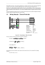
Page 186: ...ference protection should be selected where harmonics are present 2 2 Setting Example Thermal Protection MOTOR 100 1A Motor Rating Plate Data Rated output 400kW CMR Rated Voltage 3 3kV Rated Frequency 50Hz Rated Power Factor 0 85 Rated Efficiency 95 5 Service Factor NA Stall Withstand Time 11 secs cold 7 secs hot Starting Method Direct On Line Locked Rotor Current 5 x Full Load Permitted starts co...

Page 187: ...tion of the output rating of the motor Here a setting of 1 05 x 0 86 0 903 is required Itheta Thermal Overload should be set to 0 90 x In Gn 49 Motor Start Type The default setting Itheta can be used Gn 49 Motor Start Current The default value 1 5 x Itheta is chosen this is below the motor start locked rotor current and above motor f l c Gn 49 End of Start For a motor started DOL the end of the st...

Page 188: ...ighting In our example the hot cold stall withstand time ratio is 7 11 0 64 i e H C setting 64 Note that at steady state full load current the relay will stabilize at Thermal Capacity Used of 36 with this setting applied Example Motor FLC 100A Actual motor current 80A HSST 7 seconds CSST 11 seconds The thermal capacity used can be determined from the Hot Cold Curve Ratio as follows 24 70 100 100 8...

Page 189: ...ooling Constant TauC 10 H C 64 49 Capacity Alarm Setting 95 Load Alarm Setting 1 0 x Itheta Stall Protection The fundamentals of this protection feature are explained in section 2 1 2 In the example being considered the run up time is 4 seconds and the safe stall time is 11 seconds In this case the thermal characteristic gives sufficient protection for normal starting and a stalled motor condition...

Page 190: ...the system side of the relay measuring point the relay will measure pure motor current In these cases the correction does not affect the relay settings Charging of the PF correction capacitors may cause transient inrush currents during motor starting MOTOR P F Correction Capacitors where fitted 2 3 Current Protection Loss of load Undercurrent 37 Undercurrent elements are used to indicate that curr...

Page 191: ...is used the CT magnetising current losses are also reduced by a factor of three There are limits to how sensitive an earth fault relay may be set since the setting must be above any line charging current levels that can be detected by the relay On occurrence of an out of zone earth fault the elevation of sound phase voltage to earth in a non effectively earthed system can result in a zero sequence...

Page 192: ...ll The required fault setting primary operate current of the protection is chosen typically this is less than 10 of the motor rated current Additional external Non Linear Resistor and stabilising resistor components are required See separate publication Technical Guidance Note TGN High Impedance Restricted Earth Fault Protection 2 7 Voltage Protection 27 59 2 7 1 Under Voltage Power system under v...

Page 193: ...nt protects against a loss of load condition by measuring the real power flow to the motor in the running condition This provides an alternative to under current measurement as load loss may result in only a small change in current see section 2 3 To prevent spurious trip operations when the relay is first energised or when a motor is disconnected the directional power element does not operate for...

Page 194: ...nd therefore has no onerous grading requirements The CT can typically be a class 10P10 with VA rating to match the load Definite Time and Instantaneous Overcurrent For industrial systems with requirements as for i d m t l relays item a above a class 10P10 or 20 Note that overcurrent factors do not need to be high for definite time protection because once the setting is exceeded magnitude accuracy ...

Page 195: ... currents in excess of say 6 xIn 50 1 Element Current setting and time delay as required To recognise 50 1 as a General Trip set as OUTPUT CONFIG TRIP CONFIG P F Trip Trip output to be connected to output relay assigned to OUTPUT CONFIG OUTPUT MATRIX General Trip 50BCL Element 6 x In Output relay to be connected to suitably rated current break device 4 2 Backspin Protection 81B The rotor of a pump...

Page 196: ...main above minimum load level BUT below minimum fault level Operation is again subject to a time delay to prevent operation for transitory effects Alternatively a 3 Phase VT failure can be signalled to the relay via a Binary Input taken from the Trip output of an external MCB This can also be reset by a Binary Input signal VTS would not normally be used for tripping it is an alarm rather than faul...

Page 197: ... or two binary inputs mapped to the same Trip Circuit Supervision element e g 74TCS n allows the user to realise several alternative monitoring schemes TCS n Enabled Disabled 74TCS n 74TCS n 74TCS n Delay 1 74TCS n NOTE Diagram shows two binary inputs mapped to the same Trip Circuit Supervision element Figure 4 1 Logic Diagram Trip Circuit Supervision Feature 74TCS CCS n Enabled Disabled 74CCS n 7...

Page 198: ...ntact is used measures must be taken to inhibit alarm indications after a CB trip Scheme 2 Intermediate TRIP COIL 52a 52a 52b Circuit Breaker BI ve ve BO 1 BO n Remote Alarm BO R TRIP CCT n FAIL H6 Scheme Notes BI 44V 110 220V AC DC supply R 3K3 typical Figure 4 4 Trip Circuit Supervision Scheme 2 H6 Scheme 2 provides continuous Trip Circuit Supervision of trip coil with the circuit breaker Open o...

Page 199: ...rcuit Breaker H5 Scheme Notes BI 44V 110 220V AC DC supply R 3K3 typical CLOSE CCT n FAIL Figure 4 6 Close Circuit Supervision Scheme Close circuit supervision with the circuit breaker Open or Closed NOTE To achieve higher isolation in the dual TCS application it is recommended to maintain one Binary Input channel should not be connected between 110 V DC and 230 V AC control supply NOTE Use the co...

Page 200: ...sbar incomer On other systems however this output will be used to re trip the local CB to minimise potential disruption to the system if possible via a secondary trip coil and wiring The second CB Failure stage will then be used to back trip the adjacent CB s 50 BF BACK TRIP 50BF 2 Delay M RE TRIP 50BF 1 Delay S Stn Busbar Figure 4 7 Circuit Breaker Fail 50BF Setting The current setting must be se...

Page 201: ...76 842 706 79 131 92 752 197 827 7 490 35 86 247 215 619 862 477 81 621 96 070 204 053 7 683 30 88 221 220 554 882 216 84 145 99 406 210 364 7 876 25 90 192 225 480 901 923 86 704 102 767 216 760 8 069 20 92 159 230 399 921 598 89 296 106 149 223 241 8 262 15 94 124 235 310 941 243 91 922 109 560 229 805 8 455 10 96 085 240 214 960 858 94 581 113 002 236 453 8 648 5 98 044 245 111 980 444 97 274 1...

Page 202: ...160 161 054 402 636 1610 544 206 588 259 295 516 471 15 217 165 162 914 407 286 1629 147 210 645 264 561 526 614 15 411 170 164 772 411 930 1647 721 214 757 269 893 536 894 15 606 175 166 626 416 566 1666 266 218 926 275 295 547 316 15 801 180 168 478 421 195 1684 783 223 152 280 770 557 881 15 996 185 170 327 425 817 1703 270 227 437 286 320 568 593 16 191 190 172 172 430 432 1721 729 231 782 291...

Page 203: ...he control voltage is restored within the programmed restart time For example logic can be implemented to allow an auto restart delayed for up to 100s after supply loss for up to 10s The logic can be configured using Reylogic Express refer to the Reydisp Manager User Manual 5 2 Motor Start Stop The motor can be controlled from the relay fascia control mode using these settings Note that the contro...

Page 204: ...ction Devices Chapter 7 Page 31 of 31 Section 6 Application Examples 6 1 Function and Connection Diagrams M 3 1 50 BCL 50 x2 48 66 46Ph Rev 37 x2 49 14 x4 51 x2 50 BF 50N 51N 46NPS 50G 51G 50 G BF 86 74T CCS 7SR105 81B TEMP Figure 6 1 7SR105 Rho Function Diagrams ...

Page 205: ...yne Wear NE31 1TZ United Kingdom Phone 44 0 191 401 7901 Fax 44 0 191 401 5575 E mail marketing spdl gb siemens com EMDG T10067 00 76GB September 2018 For enquires please contact our Customer Support Center Phone 49 180 524 7000 24hrs Fax 49 180 524 2471 E mail support energy siemens com Subject to change without notice ...

Reviews: