background image


Answers for energy. 

7SR23 DAD 

High Impedance Protection Relay 


Reyrolle 
Protection 
Devices


Summary of Contents for 7SR23 DAD

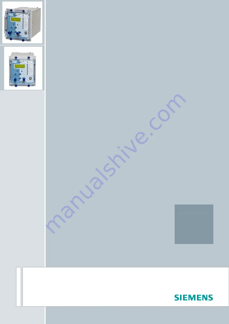
Page 1: ...Answers for energy 7SR23 DAD High Impedance Protection Relay Reyrolle Protection Devices ...

Page 2: ......

Page 3: ...ction Devices Limited Contents Technical Manual Chapters 1 Description of Operation 2 Settings Configuration Instruments 3 Performance Specification 4 Data Communications 5 Installation 6 Commissioning and Maintenance 7 Applications Guide ...

Page 4: ...7SR23 DAD Contents 2013 Siemens Protection Devices Limited ...

Page 5: ...ces Limited consent While the information and guidance given in this document is believed to be correct no liability shall be accepted for any loss or damage caused by any error or omission whether such error or omission is the result of negligence or any other cause Any and all such liability is disclaimed 2013 Siemens Protection Devices Limited 7SR23 DAD High Impedance Protection Relay Document ...

Page 6: ...Chapter 1 7SR23 DAD Description Of Operation 2013 Siemens Protection Devices Limited Chapter 1 Page 2 of 36 ...

Page 7: ... 17 3 2 Protection Measured Earth Fault 50G 18 3 3 Protection Restricted Earth Fault 87REF 19 3 4 Protection Mode Selection 20 3 4 1 3 Pole Diff REF Operation 20 3 4 2 3 Pole Diff EF Operation 21 3 4 3 REF1 REF2 Operation 22 Section 4 Control Logic Functions 23 4 1 Zone Switching 23 4 2 Quick Logic 24 Section 5 Supervision Functions 26 5 1 CT Supervision CT50 26 5 2 Sustained Fault CB Fail CB Posi...

Page 8: ...ic Diagram Measured Earth Fault Element 18 Figure 3 4 Logic Diagram Restricted Earth Fault Protection 19 Figure 3 5 Logic Diagram 3 Pole Diff REF Protection 20 Figure 3 6 Logic Diagram 3 Pole Diff EF Protection 21 Figure 3 7 Logic Diagram REF1 REF2 Protection 22 Figure 4 1 Logic Diagram Protection In Out Switching 23 Figure 4 2 Sequence Diagram showing PU DO Timers in Quick Logic Counter Reset Mod...

Page 9: ...utput visible to user Digital signal not visible to user to from another element List of settings associated with a specific function Appropriate list is TRUE when setting selected Digital signal not visible to user internal to this element IL1 Analogue signal with signal description Common setting for multiple functions c Pickup Operate Function Individual functions are enabled when associated co...

Page 10: ...tions Current Transformer Circuits The secondary circuit of a live CT must not be open circuited Non observance of this precaution can result in injury to personnel or damage to equipment External Resistors Where external resistors are fitted to relays these may present a danger of electric shock or burns if touched Fibre Optic Communication Where fibre optic communication devices are fitted these...

Page 11: ... RS485 and IRIG B 3 1 2 Standard version plus additional rear RS232 and IRIG B 4 1 2 Standard version plus additional rear Electrical Ethernet RJ45 x2 7 7 Standard version plus additional rear Optical Ethernet LC x2 8 7 Protocol IEC 60870 5 103 and Modbus RTU user selectable setting 1 IEC 60870 5 103 Modbus RTU and DNP3 0 user selectable setting 2 IEC 60870 5 103 Modbus RTU and DNP 3 0 user select...

Page 12: ...2 4 BI 11 ve ve 6 8 BI 12 ve 10 BO 9 BO 10 BO 11 BI 13 ve 12 BI 14 ve 14 BI 15 ve ve 16 18 BI 16 20 BI 17 ve 22 BI 18 ve 24 BI 19 ve ve 26 28 ve BO 12 21 19 17 BO 13 BO 14 23 25 27 BO 15 BO 16 A Analogue B PSU C Optional I O 1 2 27 28 1 2 1 2 27 28 27 28 Data Comms Optional A B C A Screen B Term 14 16 18 20 27 Rear View Arrangement of terminals and modules NOTES Shows contacts internal to relay ca...

Page 13: ...tandard panel racks The two case options have widths of 156mm E6 or 208mm E8 both have a height of 177 mm 4U See Chapter 5 Installation Guide for details of panel cut out and internal clearance requirements The complete relay assembly is withdrawable from the front of the case Contacts in the case ensure that the CT circuits remain short circuited when the relay is removed Note that when the optio...

Page 14: ...thod of controlling entering settings and retrieving data from the relay Figure 2 1 7SR23 DAD with 3 8 LEDs in E6 Case The fascia is an integral part of the relay Handles are located at each side of the element to allow it to be withdrawn from the relay case Relay Information Above the LCD three labels are provided these provide the following information 1 Product name and order code 2 Nominal cur...

Page 15: ...r to turn the screw located below the contrast symbol Turning the screw clockwise increases the contrast anti clockwise reduces the contrast PROTECTION HEALTHY LED This green LED is steadily illuminated to indicate that DC voltage has been applied to the relay power supply and that the relay is operating correctly If the internal relay watchdog detects an internal fault then this LED will continuo...

Page 16: ...s The status of hand reset LEDs is maintained by a back up storage capacitor in the event of an interruption to the d c supply voltage Standard Keys The relay is supplied as standard with five pushbuttons The buttons are used to navigate the menu structure and control relay functions They are labelled Increases a setting or moves up menu Decreases a setting or moves down menu TEST RESET Moves righ...

Page 17: ...t Where no pick up time delay has been applied the input may pick up due to induced ac voltage on the wiring connections e g cross site wiring The default pick up time of 20ms provides ac immunity Each input can be programmed independently Each input may be logically inverted to facilitate integration of the relay within the user scheme When inverted the relay indicates that the BI is energised wh...

Page 18: ...n the relay is withdrawn from the case all normally closed contacts will be open circuited This should be considered in the design of the control and protection circuitry Notes on Self Reset Outputs Outputs reset after the initiate condition is removed they are subject to the user definable Minimum Operate Time setting With a failed breaker condition the relay may remain operated until current flo...

Page 19: ...and processor ADC health checks When all checks indicate the relay is operating correctly the Protection Healthy LED is illuminated If an internal failure is detected a message will be displayed also an event will be generated and stored The relay will reset in an attempt to rectify the failure This will result in de energisation of any binary output mapped to protection healthy and flashing of th...

Page 20: ...ped with protection elements as shown in fig 3 1 Figure 3 1 Protection Functions The above illustrates the SYSTEM CONFIG Relay Config USER settings This setting gives the user access to all protection functions The relay can also be automatically configured into selected modes using the other options in the SYSTEM CONFIG Relay Config settings see section 3 4 ...

Page 21: ...quired to operate the differential element 87 50 n outputs are available for any phase or for each individual phase When 87 50 n Trip Check Logic is Enabled outputs are available when any two phases operate i e 87 50 n phase phase check Operation of the differential elements can be inhibited from Inhibit 87 50 n A binary or virtual input CT50 CT Supervision Action Inhibit Operation of the CT Super...

Page 22: ...ntaneous measured earth fault elements are provided Each element has an independent 50G n Setting setting to define the pick up current Each element has an independent 50G n Delay setting to define the operate time delay after pick up The 50G elements have transient free operation Operation of the instantaneous earth fault elements can be inhibited from Inhibit 50Gn A binary or virtual input EF In...

Page 23: ...measured by the IB current input These elements utilise RMS current values of the fundamental frequency 50 or 60Hz Two restricted earth fault elements are provided 87REF n Setting defines the current required to operate the REF element The output of 87REF n Delay can be mapped to relay outputs Operation of the REF n element can be inhibited from Inhibit 87REF n A binary or virtual input User Inhib...

Page 24: ...ult functions refer to sections 3 1and 3 3 Blk Pickup Operate 87REF 1 Setting Enable IG 87REF 1 Pickup 87REF 1 87REF 1 Delay 74 TCS x12 87 REF 1 3 1 87 50 1 87 50 2 CT50 7SR23 DAD 1 General Pickup 87 50 n Delay 87 50 n Setting Enable Inhibit 87 50 n IA IB IC Blk Pickup Operate Blk Pickup Operate Blk Pickup Operate CT50C Inhibit 87 50C n 1 CT50B Inhibit 87 50B n 1 CT50A Inhibit 87 50A n 1 87 50 n D...

Page 25: ...ons refer to sections 3 1and 3 2 Notes For details of data communications points refer to Technical Manual Chapter 4 Data Communications For details of user logic inputs and outputs refer to the relevant Reydisp Manager template 74 TCS x12 50G x2 3 1 87 50 1 87 50 2 CT50 7SR23 DAD 1 General Pickup 87 50 n Delay 87 50 n Setting Enable Inhibit 87 50 n IA IB IC Blk Pickup Operate Blk Pickup Operate B...

Page 26: ...EM CONFIG Relay Config REF1 REF2 setting When configured in this way the relay uses both 87REF elements 87REF 1 earth current is measured by the earth current input 87REF 2 current is measured by the IB current input These elements operate independently of each other For detailed information on the restricted earth fault functions refer to section 3 3 Figure 3 7 Logic Diagram REF1 REF2 Protection ...

Page 27: ...he differential protection and CT supervision monitoring is inhibited User selected output contacts assigned to CT50 are operated when Zone Switchout CT Shorting is selected to Enabled The connection of these contacts in the protection scheme ensures that any unbalance current in the differential circuit does not flow through the relay stabilising resistor Operation of the Zone Switch Out feature ...

Page 28: ... 1 Virtual I O energised 0 Virtual I O de energised Example Showing Use of Nomenclature E1 I1 F1 O2 L1 Equation 1 Binary Input 1 XOR Function Key 1 AND NOT Binary Output 2 OR LED 1 When the equation is satisfied 1 it is routed through a pick up timer En Pickup Delay a drop off timer En Dropoff Delay and a counter which instantaneously picks up and increments towards its target En Counter Target Th...

Page 29: ...Target the output of the counter En 1 and this value is held until the initiating conditions are removed when En is instantaneously reset The output of En is assigned in the OUTPUT CONFIG OUTPUT MATRIX menu where it can be programmed to any binary output O LED L or Virtual Input Output V combination Protection functions can be used in Quick Logic by mapping them to a Virtual Input Output Refer to ...

Page 30: ... 5 1 CT Supervision CT50 The CT supervision feature is phase segregated outputs are provided for individual phases Individual phases of the differential protections 87 50 can be blocked Operation of the CT Supervision elements can be inhibited from Inhibit CT50 A binary or virtual input Zone Switchout Figure 5 1 Logic Diagram CT Supervision ...

Page 31: ...nd the faulted circuit breaker s can be identified The 87 50SFM feature will pick up where 87 50 is Enabled 87 50SFM is Enabled an 87 50 n element has operated and both the Inhibit 87 50SFM and CT50 have not operated Outputs can be mapped to any combination of output contacts or LEDs outputs are available from 87 50SFM where the 87SFM DTL has elapsed 87 50BF output is issued where CB status monito...

Page 32: ...oth the CB open and CB closed positions When two auxiliary switches from a CB are monitored an alarm inhibit can be provided for the CB Don t Believe it DBI state Figure 5 3 Logic Diagram CB Position Monitoring 5 2 2 External CB Fail Input Ext 87CBF An external CB Fail initiate can utilise the CB Position monitoring feature When an external protection operates but then identifies a failed CB condi...

Page 33: ...at at least one input is energised when the trip circuit wiring is intact If all mapped inputs become de energised due to a break in the trip circuit wiring or loss of supply an output is given The 74TCS n Delay setting prevents failure being incorrectly indicated during circuit breaker operation This delay should be greater than the operating time of the circuit breaker The use of one or two bina...

Page 34: ...tion standards Communication with the relay from a personal computer PC is facilitated by the REYDISP software packages The program allows the transfer of relay settings waveform records event records fault data records Instruments meters and control functions REYDISP is compatible with IEC60870 5 103 Data communications operation is described in detail in Chapter 4 of this manual 6 2 IEC 61850 Co...

Page 35: ...nological order allowing the sequence of events to be viewed Events are also made available spontaneously to an IEC 60870 5 103 or Modbus RTU compliant control system For a complete listing of events available in each model refer to Technical Manual section 4 Data Comms 6 4 3 Waveform Records Relay waveform storage can be triggered from User selected relay operations this requires the relevant OUT...

Page 36: ...are present until CB operation When examined together the event records and the fault records will detail the full sequence of events leading to a trip Fault records are stored in a rolling buffer with the oldest faults overwritten The fault storage can be cleared with the DATA STORAGE Clear Faults setting The SYSTEM CONFIG Trip Alert Disabled setting allows the above to be switched off e g during...

Page 37: ...d DNP3 Enabled Enabled Disabled General Interrogation IEC 103 Enabled Enabled Disabled DNP3 Enabled Enabled Disabled MODBUS Enabled Enabled Enabled Changing of Settings Rear Ports when set as Remote Enabled Disabled Enabled Rear Ports when set as Local Disabled Enabled Enabled Fascia Enabled Enabled Enabled USB Disabled Enabled Enabled Historical Information Waveform Records Enabled Enabled Enable...

Page 38: ... is energised This input is leading edge triggered 6 8 3 Time Synchronisation IRIG B Optional A BNC connector on the relay rear provides an isolated IRIG B time synchronisation port The IRIG B input expects a modulated 3 6 Volt signal and provides time synchronisation to the nearest millisecond 6 9 Settings Groups The relay provides eight groups of settings Group number Gn 1 to 8 At any one time o...

Page 39: ... using the password to gain access and by entering the password NONE Again this must be entered twice to de activate the security system As soon as the user attempts to change a setting or initiate control the password is requested before any changes are allowed Once the password has been validated the user is logged on and any further changes can be made without re entering the password If no mor...

Page 40: ...Chapter 1 7SR23 DAD Description Of Operation 2013 Siemens Protection Devices Limited Chapter 1 Page 36 of 36 ...

Page 41: ...less Siemens Protection Devices Limited consent While the information and guidance given in this document is believed to be correct no liability shall be accepted for any loss or damage caused by any error or omission whether such error or omission is the result of negligence or any other cause Any and all such liability is disclaimed 2013 Siemens Protection Devices Limited 7SR23 DAD High Impedanc...

Page 42: ...Chapter 2 7SR23 DAD Settings Configuration Instruments Guide 2013 Siemens Protection Devices Limited Chapter 2 Page 2 of 18 ...

Page 43: ...nal rear RS232 IRIG B connection COM3 14 2 1 6 Optional Rear EN100 Ethernet Module COM3 15 2 1 7 Configuring Relay Data Communication 16 2 1 8 Connecting the Relay for use with Reydisp 17 APPENDIX 1 7SR23 DAD Settings List of Figures Figure 1 1 Facia of 7SR23 DAD Relay 4 Figure 1 2 Fascia Contrast symbol 4 Figure 1 3 Relay Identifier Screen 5 Figure 1 4 Menu 5 Figure 1 5 7SR23 DAD Menu Structure 6...

Page 44: ... settings in the relay from the fascia Instruments Mode allows the user to view the relay meters and configure favourite instrument views which will cycle on the LCD automatically when the relay is unattended Fault Data Mode allows the user to view the type and data of any protection operation of the relay Control Mode allows the user to control selected relay functionality if allowed by the contr...

Page 45: ... power on the screen that was showing prior to the last power off will be displayed The push buttons on the fascia are used to display and edit the relay settings via the LCD to display and activate the control segment of the relay to display the relays instrumentation and Fault data and to reset the output relays and LED s The menus can be viewed via the LCD by pressing the access keys as below F...

Page 46: ... up in the menu structure Pressed repeatedly will return to the Relay Identifier screen It is also used to reject any alterations to a setting while in the edit mode This push button is used to Reset the fault indication on the fascia from the Relay Identifier screen Test front fascia LEDs from the Relay Identifier screen i e when pressed all LEDs will momentarily light up to indicate their correc...

Page 47: ...If the relay is setting password protected the user will be asked to enter the password If an incorrect password is entered editing will not be permitted All screens can be viewed even if the password is not known While a setting is being edited flashing characters indicate the edit field Pressing the or buttons will display the valid field values If these buttons are held on the rate of scrolling...

Page 48: ...press ENTER again and this meter will be removed from the FAVOURITE METERS sub group The relay will poll through displaying each of the meters selected in favourite meters after no key presses have been detected for a user settable period of time The time is set in the Setting menu System Config Favourite Meters Timer CURRENT METERS to view This is the sub group that includes all the meters that a...

Page 49: ...last reset GENERAL ALARM METERS to view This is the sub group that includes all the meters that are associated with the Binary inputs TEST RESET allows access to this sub group General Alarms ALARM n Cleared Displays the state of General Alarm BINARY INPUT METERS to view This is the sub group that includes all the meters that are associated with the Binary inputs TEST RESET allows access to this s...

Page 50: ...ports are currently active COM1 TRAFFIC Tx1 0 Rx1 0 Rx1 Errors 0 Displays traffic on Com1 COM2 TRAFFIC Tx2 0 Rx2 0 Rx2 Errors 0 Displays traffic on Com2 COM3 TRAFFIC Tx3 0 Rx3 0 Rx3 Errors 0 Displays traffic on Com3 when fitted COM4 TRAFFIC Tx4 0 Rx4 0 Rx4 Errors 0 Displays traffic on Com4 when fitted MISCELLANEOUS METERS to view This is the sub group that includes indication such as the relays ti...

Page 51: ... 0 0 0 CNT 0 1 0 En Equation 1 5 Fault Data Mode The Fault Data Mode sub menu lists the time and date of the previous ten protection operations The stored data about each fault can be viewed by pressing the TEST RESET button Each record contains data on the operated elements analogue values and LED flag states at the time of the fault The data is viewed by scrolling down using the button ...

Page 52: ...er specific time current curves To configure the relay using a serial communication port the user will need the following PC with Reydisp installed This can be download from our website www energy siemens com Configuration and download of IEC 61850 data and programming of graphical user logic requires the use of the Reydisp Manager software which is supplied with online instructions and help and i...

Page 53: ...x Tx Rx USB or 9 pin male D connector 25 pin male D connector 62 5 125µm fibre optic with ST connectors Laptop computer RS232 straight through cable or RS232 to USB converter cable Figure 2 3 Fibre Optic Connection to PC Sigma devices have a 25 pin female D connector with the following pin out Pin Function 2 Transmit Data 3 Received Data 4 Request to Send 5 Clear to Send 6 Data set ready 7 Signal ...

Page 54: ...B or 9 pin male D connector RS485 Screened twisted pair 7SR Figure 2 4 Additional Optional rear RS485 IRIG B connection to a PC 2 1 5 Optional rear RS232 IRIG B connection COM3 Figure 2 5 Additional Optional rear RS232 IRIG B connection to a PC Pin Relay Function 1 Not Connected 2 Receive Data RXD 3 Transmit Data TXD 4 Outut Supply 5 V 50mA 5 Signal Ground GND 6 Input Supply 5 V 50mA 7 Linked to 8...

Page 55: ...uplex LC fibre optic connectors Setting name Range Default Setting Notes LAN Protocol OFF IEC60870 5 103 IEC60870 5 103 If this setting is set to Off access to relay data using Reydisp Evolution and Reydisp Manager software via the Ethernet interface is not available Connections to the optional EN100 ethernet module are made on the rear underside of the relay Connections are made to either RJ45 so...

Page 56: ...70 5 103 COM1 RS485 Mode Local Remote Local or Remote Remote COM1 RS485 Baud Rate 75 110 150 300 600 1200 2400 4800 9600 19200 38400 19200 COM1 RS485 Parity NONE ODD EVEN EVEN COM1 Rear mounted RS485 port COM2 USB Protocol OFF IEC60870 5 103 MODBUS RTU ASCII DNP3 IEC60870 5 103 COM2 USB Mode Local Remote Local or Remote Remote COM2 Front USB port COM3 Protocol OFF IEC60870 5 103 MODBUS RTU DNP3 IE...

Page 57: ...ll available communication ports of the PC will automatically be detected On the start page tool bar open up the sub menu File Connect The Communication Manager window will display all available communication ports With the preferred port highlighted select the Properties option and ensure the baud rate and parity match that selected in the relay Data Comms settings Select Connect to initiate the ...

Page 58: ...Chapter 2 7SR23 DAD Settings Configuration Instruments Guide 2013 Siemens Protection Devices Limited Chapter 2 Page 18 of 18 ...

Page 59: ...mens Protection Devices Limited consent While the information and guidance given in this document is believed to be correct no liability shall be accepted for any loss or damage caused by any error or omission whether such error or omission is the result of negligence or any other cause Any and all such liability is disclaimed 2013 Siemens Protection Devices Limited 7SR23 DAD High Impedance Protec...

Page 60: ...Chapter 3 7SR23 DAD Performance Specification 2013 Siemens Protection Devices Limited ...

Page 61: ...ection 2 Protection Functions 15 2 1 50G Instantaneous Measured Earth Fault 15 2 1 1 Reference 15 2 1 2 Operate and Reset Level 15 2 1 3 Operate and Reset Time 15 2 2 87 50 High Impedance Differential Protection 16 2 2 1 Reference 16 2 2 2 Operate and Reset Level 16 2 2 3 Operate and Reset Time 16 2 2 4 Harmonic Rejection 16 2 3 87REF Restricted Earth Fault Protection 17 2 3 1 Reference 17 2 3 2 O...

Page 62: ...l 1 1 1 Certification CE Conformity This product is CE compliant to relevant EU directives 1 1 2 Reference 1 1 2 1 Accuracy Reference Conditions This product has been tested under the following conditions unless specifically stated otherwise Parameter Value Auxiliary supply Nominal AC Current Nominal Frequency Nominal Ambient temperature 20 C ...

Page 63: ...ght 9 0W Quiescent typical 7 3W 48V DC Quiescent backlight 8 8W Quiescent typical 6 8W 110V DC Quiescent backlight 8 1W Quiescent typical 6 4W 220V DC Quiescent backlight 7 7W Typical for relay size E8 When supplied with additional Ethernet communication interface the above burdens are increased by 2 5W 1 2 1 2 DC Supply Variation IEC 60255 6 IEC 60255 11 Quantity Value Allowable superimposed ac c...

Page 64: ...suring Range In 1 5 A Phase and earth 8 x In fn 50 60Hz 47 to 63Hz Note 1 A and 5 A nominal inputs are user selectable on each model 1 2 2 1 Burden 1 2 2 2 Thermal Withstand IEC 60255 27 Overload Current Phase and Earth Overload Period 1A 5A Continuous 4 xIn 1 second 100A 350A Value Phase and Earth Attribute 1A 5A AC Burden 0 1 VA 0 3 VA ...

Page 65: ... VBI 88 VDC 74 to 290 VDC 1 2 4 1 Performance Attribute Value VBI 19 V 1 5mA Maximum DC current for operation VBI 88 V 1 5mA Reset Operate voltage ratio 90 Response time 7ms Response time when programmed to energise an output relay contact i e includes output relay operation 20ms The binary inputs have a low minimum operate current and may be set for high speed operation Where a binary input is bo...

Page 66: ...inal 87 5 137 5V Operative IOP 50mA 1K2 330 BI DTL 10ms 10µF 60V Capacitance discharge BI DTL 10ms 10µF 150V Capacitance discharge BI 19V BI 19V BI 19V BI 19V BI 19V Resistor power ratings 30V DC Nominal 3W 48V DC Nominal 3W 110V DC Nominal 10W ESI 1 110V DC Nominal 20W ESI 2 Resistors must be wired with crimped connections as they may run hot 110V DC Nominal 87 5 137 5V Operative IOP 25mA 2K7 110...

Page 67: ...20nm Launch power into recommended fibre 16 dBm Receiver sensitivity 24 dBm 1 3 2 3 RS485 Data Communication Interface Standard Rear Port Attribute Value Physical layer Electrical Connectors 4mm Ring Crimp 1 3 2 4 RS485 Data Communication Interface Optional Rear Mounted Port COM3 Attribute Value Physical layer Electrical Connectors 4 way Plug 1 3 2 5 RS232 Data Communication Interface Optional Rea...

Page 68: ...t Voltage with regard to socket 500 VAC 50 Hz Bridgeable distance 20m 1 3 3 Real Time Clock 1 3 3 1 Internal Clock The specification below applies only while no external synchronisation signal e g IRIG B IEC 60870 5 103 is being received Attribute Value 3 5 ppm No auxiliary supply connected Accuracy 40 to 85o C 100 ppm Auxiliary supply connected 1 3 3 2 IRIG B Attribute Value Connector BNC Signal ...

Page 69: ...nsulation HV Dielectric Withstand IEC 60255 5 Type Level Between any terminal and earth Between independent circuits 2 0 kV AC RMS for 1 min Across normally open contacts 1 0 kV AC RMS for 1 min 1 4 2 2 Transient Overvoltage IEC 60255 5 Type Level Between all terminals and earth or between any two independent circuits 5 0 kV 1 2 50 s 0 5j 1 4 2 3 Radiated Radio Frequency Emissions IEC 60255 25 Typ...

Page 70: ...y Radiated Electromagnetic Field Disturbance IEC 60255 22 3 Class III Type Level Variation 80 MHz to 1000 MHz 10 V m 5 1 4 2 8 Electrical Fast Transient Burst Immunity IEC 60255 22 4 Class A 2002 Type Level Variation Case Aux Power I O 4kV 10 RS485 Metallic Comms 2 0 kV No data loss 1 4 2 9 Surge Immunity IEC 60255 22 5 IEC 61000 4 5 Type Level Variation Analog Inputs Line to Earth 4 0 kV Case Aux...

Page 71: ...50Hz 1 4 3 Mechanical Environment 1 4 3 1 Vibration Sinusoidal IEC 60255 21 1 Class I Type Level Variation Vibration response 0 5 gn Vibration endurance 1 0 gn 5 1 4 3 2 Shock and Bump IEC 60255 21 2 Class I Type Level Variation Shock response 5 gn 11 ms Shock withstand 15 gn 11 ms Bump test 10 gn 16 ms 5 1 4 3 3 Seismic IEC 60255 21 3 Class I Type Level Variation Seismic response Horizontal 1 gn ...

Page 72: ... from front of panel 31 mm 42mm inc pushbuttons when fitted See appropriate case outline and panel drilling drawing as specified in Diagrams and Parameters document for complete dimensional specifications Mounting front of panel flush mounting or 19 rack mounting 1 5 1 2 Weights Parameter Value 7SR23 DAD E6 case 4 3kg Weight 7SR23 DAD E8 case 5 5kg Additional weights to the above typical Optional ...

Page 73: ...01 5 5 1 60s 2 1 2 Operate and Reset Level Attribute Value Iop Operate level 100 Is 5 or 1 In Reset level 95 Iop or 1 In Repeatability 1 Transient overreach X R 100 5 10 C to 55 C 5 Variation fnom 5 5 2 1 3 Operate and Reset Time Attribute Value 2 xIs 22ms 5ms 50Hz 2 xIs 18ms 5ms 60Hz 3 xIs 1 cycle 5ms tbasic Element basic operate time 5 xIs 1 cycle top Operate time following delay tbasic td 1 or ...

Page 74: ...ute Value Iop Operate level 100 Is 5 or 1 xIn Reset level 95 Iop 5 or 1 xIn Repeatability 1 Transient overreach X R 100 5 10 C to 55 C 5 Variation fnom 5 5 2 2 3 Operate and Reset Time Attribute Value 2 xIs 22ms 5ms 50Hz 2 xIs 18ms 5ms 60Hz 3 xIs 1 cycle 5ms tbasic Element basic operate time 5 xIs 1 cycle top Operate time following delay tbasic td 1 or 10ms Repeatability 1 or 10ms Overshoot time 4...

Page 75: ... Value Iop Operate level 100 Is 5 or 1 xIn Reset level 95 Iop 5 or 1 xIn Repeatability 1 Transient overreach X R 100 5 10 C to 55 C 5 Variation fnom 5 5 2 3 3 Operate and Reset Time Attribute Value 2 xIs 22ms 5ms 50Hz 2 xIs 18ms 5ms 60Hz 3 xIs 1 cycle 5ms tbasic Element basic operate time 5 xIs 1 cycle top Operate time following delay tbasic td 1 or 10ms Repeatability 1 or 10ms Overshoot time 40 m...

Page 76: ...Delay setting 0 0 005 1 0 1 01 5 5 1 60s 3 1 2 Operate and Reset Level Attribute Value Iop Operate level 100 Is 5 or 1 xIn Reset level 95 Iop 5 or 1 xIn Repeatability 1 Transient overreach X R 100 5 10 C to 55 C 5 Variation fnom 5 5 3 1 3 Operate and Reset Time Attribute Value tbasic Element basic operate time 2 xIs 1 5 cycles 5ms top Operate time following delay tbasic td 1 or 10ms Repeatability ...

Page 77: ...9 of 20 3 2 74TCS Trip Circuit Supervision 3 2 1 Reference Parameter Value td Delay setting 0 0 02 60 s 3 2 2 Operate and Reset Time Attribute Value tbasic Element basic operate time 30ms 10ms top Operate time following delay tbasic td 1 or 20ms Repeatability 1 or 10ms 10 C to 55 C 5 Variation fnom 5 5 ...

Page 78: ...Chapter 3 7SR23 DAD Performance Specification 2013 Siemens Protection Devices Limited Chapter 3 Page 20 of 20 ...

Page 79: ...s Protection Devices Limited consent While the information and guidance given in this document is believed to be correct no liability shall be accepted for any loss or damage caused by any error or omission whether such error or omission is the result of negligence or any other cause Any and all such liability is disclaimed 2013 Siemens Protection Devices Limited 7SR23 DAD High Impedance Protectio...

Page 80: ...Chapter 4 7SR23 DAD Data Communications 2013 Siemens Protection Devices Limited Chapter 4 Page 2 of 54 ...

Page 81: ...vice Profile 31 5 2 Implementation Table 34 5 3 Point List 39 Section 6 IEC61850 Protocol Support 52 Section 7 Modems 53 7 1 1 Connecting a Modem to the Relay s 53 7 1 2 Setting the Remote Modem 53 7 1 3 Connecting to the Remote Modem 53 Section 8 Glossary 54 List of Figures Figure 2 1 Communication to Front USB Port 6 Figure 2 2 Communication to Multiple Devices using RS485 Standard Port 7 Figure...

Page 82: ...he relay data communication facility incorporates user selectable protocols to provide compatibility with control and automation systems This section specifies connection details and lists the events commands and measurands available in the IEC60870 5 103 Modbus RTU DNP3 0 and optional IEC61850 protocols When IEC60870 5 103 protocol is selected the relay can communicate with PCs running Reydisp so...

Page 83: ...MODBUS RTU or optional DNP3 are also available via COM2 An ASCII protocol the main use of which is to allow firmware to be updated from the front connection is also available through this port Access to COM2 settings is only available from the relay front fascia via the COMMUNICATIONS MENU 3 COM3 Located on the rear of the relay this optional port can be used for IEC60870 5 103 MODBUS RTU DNP 3 or...

Page 84: ...equire a suitable USB driver to be installed this will be carried out automatically when the Reydisp software is installed When the Reydisp software is running with the USB cable connected to a device an additional connection is shown Connections to these devices are not shown when they are not connected The USB communication interface on the relay is labelled Com 2 and its associated settings are...

Page 85: ...e necessary The following settings must be configured when using the RS485 interface Setting name Range Default Setting Notes COM1 RS485 Protocol OFF IEC60870 5 103 MODBUS RTU DNP3 0 IEC60870 5 103 As Required Sets the protocol used to communicate on the standard RS485 connection COM1 RS485 Baud Rate 75 110 150 300 600 1200 2400 4800 9600 19200 38400 19200 As Required The baud rate set on all of t...

Page 86: ... dB Fibre Type Min Max Min Max 62 5 125µm 11 7 15 7 24 9 2 1mm Polymer 6 4 10 4 24 9 2 200µm PCS 2 8 6 8 24 9 2 Factors to be considered when calculating fibre optic transmission distances Transmitter launch power Attenuation based on light frequency fibre material and fibre diameter Number of intermediate connectors and splices Receiver sensitivity The light power at the receiver must be above th...

Page 87: ...calculations A Launch power dB B Fibre Type C Loss dB km dB km D Length km E Total fibre loss CxD dB F No of Splices G Loss at each splice dB H Total loss at splices FxG dB I No of connectors J Loss per connector dB K Total loss at connectors IxJ dB L Total losses E H K dB M Receive power budget A L dB N Safety Margin dB O Device Receive Sensitivity dB ...

Page 88: ... and in accordance with the master device COM3 Line Idle LIGHT ON LIGHT OFF LIGHT OFF As Required Sets the idle state of the line in accordance with master device COM3 Data Echo ON OFF OFF As Required Set to ON when relays are connected in a ring configuration COM4 Protocol OFF IEC60870 5 103 MODBUS RTU DNP3 0 IEC60870 5 103 As Required Sets the protocol used to communicate on the connection Com4 ...

Page 89: ...13 Siemens Protection Devices Limited Chapter 4 Page 11 of 54 Figure 2 3 Communication to Multiple Devices using Fibre optic Ring Network Figure 2 4 Communication to Multiple Devices from Control System and Laptop using Fibre optic Star Network ...

Page 90: ... Screened twisted pair 7SR24 Figure 2 5 Additional Optional Rear RS485 IRIG B Connection to a PC 2 1 5 Optional Rear RS232 COM3 Figure 2 6 Additional Optional Rear RS232 IRIG B Connection to a PC Pin Relay Function 1 Not Connected 2 Receive Data RXD 3 Transmit Data TXD 4 Output Supply 5V 50mA 5 Signal Ground GND 6 Output Supply 5V 50mA 7 Linked to 8 volts free 8 Linked to 7 volts free 9 Output Sup...

Page 91: ...ibre optic connectors Setting name Range Default Setting Notes LAN Protocol OFF IEC60870 5 103 IEC60870 5 103 If this setting is set to Off access to relay data using Reydisp Evolution and Reydisp Manager software via the Ethernet interface is not available Connections to the optional EN100 ethernet module are made on the rear underside of the relay Connections are made to either RJ45 sockets elec...

Page 92: ... Address Valid settings are within the range 1 254 a relay with the default address of 0 will not be able to communicate Cause of Transmission The cause of transmission COT column of the Information Number and Function table lists possible causes of transmission for these frames The following abbreviations are used Abbreviation Description SE spontaneous event T test mode GI general interrogation ...

Page 93: ...x 1 1 9 60 182 Quick Logic E1 x 1 1 9 60 183 Quick Logic E2 x 1 1 9 60 184 Quick Logic E3 x 1 1 9 60 185 Quick Logic E4 x 1 1 9 60 186 Quick Logic E5 x 1 1 9 60 187 Quick Logic E6 x 1 1 9 60 188 Quick Logic E7 x 1 1 9 60 189 Quick Logic E8 x 1 1 9 60 190 Quick Logic E9 x 1 1 9 60 191 Quick Logic E10 x 1 1 9 60 192 Quick Logic E11 x 1 1 9 60 193 Quick Logic E12 x 1 1 9 60 194 Quick Logic E13 x 1 1 ...

Page 94: ... 1 9 80 1 Binary Output 1 x 1 1 9 80 2 Binary Output 2 x 1 1 9 80 3 Binary Output 3 x 1 1 9 80 4 Binary Output 4 x 1 1 9 80 5 Binary Output 5 x 1 1 9 80 6 Binary Output 6 x 1 1 9 80 7 Binary Output 7 x 1 1 9 80 8 Binary Output 8 x 1 1 9 80 9 Binary Output 9 x 1 1 9 80 10 Binary Output 10 x 1 1 9 80 11 Binary Output 11 x 1 1 9 80 12 Binary Output 12 x 1 1 9 80 13 Binary Output 13 x 1 1 9 80 14 Bina...

Page 95: ...9 186 1 CB1 Cct Closed Alarm x 1 1 9 186 2 CB2 Cct Closed Alarm x 1 1 9 186 3 CB3 Cct Closed Alarm x 1 1 9 186 4 CB4 Cct Closed Alarm x 1 1 9 186 5 CB5 Cct Closed Alarm x 1 1 9 186 6 CB6 Cct Closed Alarm x 1 1 9 186 7 CB7 Cct Closed Alarm x 1 1 9 186 8 CB8 Cct Closed Alarm x 1 1 9 186 9 CB9 Cct Closed Alarm x 1 1 9 186 10 CB10 Cct Closed Alarm x 1 1 9 186 11 CB11 Cct Closed Alarm x 1 1 9 186 12 CB...

Page 96: ...0CG 1 x 2 1 9 186 143 87 50A 2 x 2 1 9 186 144 87 50B 2 x 2 1 9 186 145 87 50C 2 x 2 1 9 186 146 87 50G 2 x 2 1 9 186 147 87 50AB 2 x 2 1 9 186 148 87 50BC 2 x 2 1 9 186 149 87 50CA 2 x 2 1 9 186 150 87 50AG 2 x 2 1 9 186 151 87 50BG 2 x 2 1 9 186 152 87 50CG 2 x 2 1 9 186 154 CT50A x 2 1 9 186 155 CT50B x 2 1 9 186 156 CT50C x 2 1 9 186 157 CT50G x 2 1 9 186 158 87REF x 2 1 9 186 159 87REF 1 x 2 ...

Page 97: ...nt 1 1 186 209 CB6 Total Open Count ASDU4 1 1 186 210 CB6 Delta Open Count ASDU4 1 1 186 211 CB7 Total Open Count x 1 1 9 186 212 CB7 Delta Open Count x 1 1 9 186 213 Reset CB7 Total Open Count 1 1 186 214 Reset CB7 Delta Open Count 1 1 186 215 CB7 Total Open Count ASDU4 1 1 186 216 CB7 Delta Open Count ASDU4 1 1 186 217 CB8 Total Open Count x 1 1 9 186 218 CB8 Delta Open Count x 1 1 9 186 219 Res...

Page 98: ...0 3 CB 3 x 1 1 9 200 4 CB 4 x 1 1 9 200 5 CB 5 x 1 1 9 200 66 CB 6 x 1 1 9 200 67 CB 7 x 1 1 9 200 68 CB 8 x 1 1 9 200 69 CB 9 x 1 1 9 200 70 CB 10 x 1 1 9 200 71 CB 11 x 1 1 9 200 72 CB 12 x 1 1 9 255 0 GI End 8 10 255 0 Time Synchronization 6 8 Table 2 IEC60870 5 103 Measurand FUN INF Description Function Type COT 186 253 Measurand IL1 2 3 IL1 1 2 x IL2 1 2 x IL3 1 2 x Ig 1 2 x 9 Cyclic Refresh ...

Page 99: ...2 Settings Group 7 Select ON 20 20 181 113 Settings Group 8 Select ON 20 20 186 127 E F Out In ON OFF 20 20 186 161 Zone Switch Out In ON OFF 20 20 186 171 Reset CB Total Trip Count ON 20 20 186 172 Reset CB Delta Trip Count ON 20 20 186 177 Reset CB1 Total Open Count ON 20 20 186 178 Reset CB1 Delta Open Count ON 20 20 186 183 Reset CB2 Total Open Count ON 20 20 186 184 Reset CB2 Delta Open Count...

Page 100: ... 4 ON 20 20 200 154 User SP Command 5 ON 20 20 200 155 User SP Command 6 ON 20 20 200 156 User SP Command 7 ON 20 20 200 157 User SP Command 8 ON 20 20 200 158 User DP Command 1 ON OFF 20 20 200 159 User DP Command 2 ON OFF 20 20 200 160 User DP Command 3 ON OFF 20 20 200 161 User DP Command 4 ON OFF 20 20 200 162 User DP Command 5 ON OFF 20 20 200 163 User DP Command 6 ON OFF 20 20 200 164 User D...

Page 101: ...us RTU Coils Read Write Address Description Write Only 00001 Binary Output 1 00002 Binary Output 2 00003 Binary Output 3 00004 Binary Output 4 00005 Binary Output 5 00006 Binary Output 6 00007 Binary Output 7 00008 Binary Output 8 00009 Binary Output 9 00010 Binary Output 10 00011 Binary Output 11 00012 Binary Output 12 00013 Binary Output 13 00014 Binary Output 14 00015 Binary Output 15 00016 Bin...

Page 102: ... 00150 Reset CB9 Delta Cnt Yes 00151 Reset CB10 Open Cnt Yes 00152 Reset CB10 Delta Cnt Yes 00153 Reset CB11 Open Cnt Yes 00154 Reset CB11 Delta Cnt Yes 00155 Reset CB12 Open Cnt Yes 00156 Reset CB12 Delta Cnt Yes 00165 Reset Start Count Yes 00200 User SP Command 1 Yes 00201 User SP Command 2 Yes 00202 User SP Command 3 Yes 00203 User SP Command 4 Yes 00204 User SP Command 5 Yes 00205 User SP Comm...

Page 103: ...p 10102 General Trip 10103 Start Pick up L1 10104 Start Pick up L2 10105 Start Pick up L3 10106 Start Pick up N 10107 Trip L1 10108 Trip L2 10109 Trip L3 10111 Trip Circuit Fail 10120 Local Mode 10121 Remote Mode 10122 Service Mode 10123 Local Remote 10130 Trip Circuit Fail 1 10131 Trip Circuit Fail 2 10132 Trip Circuit Fail 3 10133 Trip Circuit Fail 4 10134 Trip Circuit Fail 5 10135 Trip Circuit ...

Page 104: ...tart 10802 Re Start 12500 General Alarm 1 12501 General Alarm 2 12502 General Alarm 3 12503 General Alarm 4 12504 General Alarm 5 12505 General Alarm 6 12506 General Alarm 7 12507 General Alarm 8 12508 General Alarm 9 12509 General Alarm 10 12510 General Alarm 11 12511 General Alarm 12 12512 Quick Logic E1 12513 Quick Logic E2 12514 Quick Logic E3 12515 Quick Logic E4 12516 Quick Logic E5 12517 Qu...

Page 105: ...ind Spot 12700 CB Trip Count Target 12701 CB Delta Cnt Target 12702 CB1 Open Cnt Target 12703 CB1 Delta Cnt Target 12704 CB2 Open Cnt Target 12705 CB2 Delta Cnt Target 12706 CB3 Open Cnt Target 12707 CB3 Delta Cnt Target 12708 CB4 Open Cnt Target 12709 CB4 Delta Cnt Target 12710 CB5 Open Cnt Target 12711 CB5 Delta Cnt Target 12712 CB6 Open Cnt Target 12713 CB6 Delta Cnt Target 12714 CB7 Open Cnt T...

Page 106: ... Alarm 12756 CB9 Cct DBI Alarm 12757 CB10 Cct DBI Alarm 12758 CB11 Cct DBI Alarm 12759 CB12 Cct DBI Alarm 12770 CB1 Travel Alarm 12771 CB2 Travel Alarm 12772 CB3 Travel Alarm 12773 CB4 Travel Alarm 12774 CB5 Travel Alarm 12775 CB6 Travel Alarm 12776 CB7 Travel Alarm 12777 CB8 Travel Alarm 12778 CB9 Travel Alarm 12779 CB10 Travel Alarm 12780 CB11 Travel Alarm 12781 CB12 Travel Alarm 12800 Ext 87CBF...

Page 107: ...32BITS_3DP 1 A 30356 Ia Secondary A FP_32BITS_3DP 1 A 30358 Ib Secondary A FP_32BITS_3DP 1 A 30360 Ic Secondary A FP_32BITS_3DP 1 A 30362 Ia Nominal Magnitude xIn FP_32BITS_3DP 1 X In 30364 Ib Nominal Magnitude xIn FP_32BITS_3DP 1 X In 30366 Ic Nominal Magnitude xIn FP_32BITS_3DP 1 X In 32500 CB Trip Cnt 2 Registers 32502 CB Delta Trip Cnt 2 Registers 32504 CB1 Open Cnt 2 Registers 32506 CB1 Delta...

Page 108: ... 1 X In 40366 Ic Nominal Magnitude xIn FP_32BITS_3DP 1 X In 42500 CB Trip Cnt 2 Registers 42502 CB Delta Trip Cnt 2 Registers 42504 CB1 Open Cnt 2 Registers 42506 CB1 Delta Open Cnt 2 Registers 42508 CB2 Open Cnt 2 Registers 42510 CB2 Delta Open Cnt 2 Registers 42512 CB3 Open Cnt 2 Registers 42514 CB3 Delta Open Cnt 2 Registers 42516 CB4 Open Cnt 2 Registers 42518 CB4 Delta Open Cnt 2 Registers 42...

Page 109: ...ource Code Library Version 3 Highest DNP Level Supported For Requests Level 3 For Responses Level 3 Device Function Master Slave Notable objects functions and or qualifiers supported in addition to the Highest DNP Levels Supported the complete list is described in the attached table For static non change event object requests request qualifier codes 07 and 08 limited quantity and 17 and 28 index a...

Page 110: ...t Applicable Frozen Counter Change Event Scan Period Unsupported Not Applicable String Change Event Scan Period Unsupported Not Applicable Virtual Terminal Event Scan Period Unsupported Not Applicable Sends Executes Control Operations WRITE Binary Outputs Never Always Sometimes Configurable SELECT OPERATE Never Always Sometimes Configurable DIRECT OPERATE Never Always Sometimes Configurable DIRECT...

Page 111: ...us Flags Change No other options are permitted Default Counter Object Variation No Counters Reported Configurable Default Object Default Variation Point by point list attached Counters Roll Over at No Counters Reported Configurable attach explanation 16 Bits 32 Bits Other Value _____ Point by point list attached Sends Multi Fragment Responses Yes No Configurable Sequential File Transfer Support Fi...

Page 112: ...ange Any Variation 1 read 06 no range or all 07 08 limited qty 2 1 Binary Input Change without Time 1 read 06 no range or all 07 08 limited qty 129 response 130 unsol resp 17 28 index 2 2 Binary Input Change with Time 1 read 06 no range or all 07 08 limited qty 129 response 130 unsol resp 17 28 index 2 3 default 1 Binary Input Change with Relative Time 1 read 06 no range or all 07 08 limited qty 1...

Page 113: ...esponse 00 01 start stop 17 28 index see note 2 20 3 32 Bit Delta Counter with Flag 20 4 16 Bit Delta Counter with Flag 20 5 default see note 1 32 Bit Binary Counter without Flag 1 read 00 01 start stop 06 no range or all 07 08 limited qty 17 27 28 index 129 response 00 01 start stop 17 28 index see note 2 20 6 16 Bit Binary Counter without Flag 1 read 00 01 start stop 06 no range or all 07 08 lim...

Page 114: ...9 default see note 1 32 Bit Frozen Counter without Flag 1 read 00 01 start stop 06 no range or all 07 08 limited qty 17 27 28 index 129 response 00 01 start stop 17 28 index see note 2 21 10 16 Bit Frozen Counter without Flag 1 read 00 01 start stop 06 no range or all 07 08 limited qty 17 27 28 index 129 response 00 01 start stop 17 28 index see note 2 21 11 32 Bit Frozen Delta Counter without Fla...

Page 115: ...ounter Event with Time 1 read 06 no range or all 07 08 limited qty 129 response 130 unsol resp 17 28 index 23 7 32 Bit Frozen Delta Counter Event with Time 23 8 16 Bit Frozen Delta Counter Event with Time 30 0 Analog Input Any Variation 1 read 22 assign class 00 01 start stop 06 no range or all 07 08 limited qty 17 27 28 index 30 1 32 Bit Analog Input 1 read 00 01 start stop 06 no range or all 07 ...

Page 116: ...08 limited qty 129 response 130 unsol resp 17 28 index 32 8 long floating point Analog Change Event with Time 1 read 06 no range or all 07 08 limited qty 129 response 130 unsol resp 17 28 index 50 0 Time and Date 1 read 07 limited qty 1 129 response 07 limited qty 1 50 1 default 1 Time and Date 2 write 07 limited qty 1 50 3 Time and Date Last Recorded Time 2 write 07 limited qty 51 1 Time and Date...

Page 117: ... 1 2 2 2 2 Binary Input 2 2 2 2 3 Binary Input 3 2 2 2 4 Binary Input 4 2 2 2 5 Binary Input 5 2 2 2 6 Binary Input 6 2 2 2 7 Binary Input 7 2 2 2 8 Binary Input 8 2 2 2 9 Binary Input 9 2 2 2 10 Binary Input 10 2 2 2 11 Binary Input 11 2 2 2 12 Binary Input 12 2 2 2 13 Binary Input 13 2 2 2 14 Binary Input 14 2 2 2 15 Binary Input 15 2 2 2 16 Binary Input 16 2 2 2 17 Binary Input 17 2 2 2 18 Bina...

Page 118: ...neral Alarm 12 2 2 2 141 Quick Logic E1 2 2 2 142 Quick Logic E2 2 2 2 143 Quick Logic E3 2 2 2 144 Quick Logic E4 2 2 2 145 Quick Logic E5 2 2 2 146 Quick Logic E6 2 2 2 147 Quick Logic E7 2 2 2 148 Quick Logic E8 2 2 2 149 Quick Logic E9 2 2 2 150 Quick Logic E10 2 2 2 151 Quick Logic E11 2 2 2 152 Quick Logic E12 2 2 2 153 Quick Logic E13 2 2 2 154 Quick Logic E14 2 2 2 155 Quick Logic E15 2 2 ...

Page 119: ...50A 1 2 2 2 304 87 50B 1 2 2 2 305 87 50C 1 2 2 2 306 87 50G 1 2 2 2 307 87 50AB 1 2 2 2 308 87 50BC 1 2 2 2 309 87 50CA 1 2 2 2 310 87 50AG 1 2 2 2 311 87 50BG 1 2 2 2 312 87 50CG 1 2 2 2 313 87 50A 2 2 2 2 314 87 50B 2 2 2 2 315 87 50C 2 2 2 2 316 87 50G 2 2 2 2 317 87 50AB 2 2 2 2 318 87 50BC 2 2 2 2 319 87 50CA 2 2 2 2 320 87 50AG 2 2 2 2 321 87 50BG 2 2 2 2 322 87 50CG 2 2 2 2 323 CT50 2 2 2 ...

Page 120: ... CB11 Open Cnt 2 2 2 363 CB11 Delta Cnt 2 2 2 364 CB12 Open Cnt 2 2 2 365 CB12 Delta Cnt 2 2 2 381 CB1 Cct Close Alarm 2 2 2 382 CB2 Cct Close Alarm 2 2 2 383 CB3 Cct Close Alarm 2 2 2 384 CB4 Cct Close Alarm 2 2 2 385 CB5 Cct Close Alarm 2 2 2 386 CB6 Cct Close Alarm 2 2 2 387 CB7 Cct Close Alarm 2 2 2 388 CB8 Cct Close Alarm 2 2 2 389 CB9 Cct Close Alarm 2 2 2 390 CB10 Cct Close Alarm 2 2 2 391 ...

Page 121: ... 2 2 2 453 Ext 87CBF3 2 2 2 454 Ext 87CBF4 2 2 2 455 Ext 87CBF5 2 2 2 456 Ext 87CBF6 2 2 2 457 Ext 87CBF7 2 2 2 458 Ext 87CBF8 2 2 2 459 Ext 87CBF9 2 2 2 460 Ext 87CBF10 2 2 2 461 Ext 87CBF11 2 2 2 462 Ext 87CBF12 2 2 2 501 Virtual 1 2 2 2 502 Virtual 2 2 2 2 503 Virtual 3 2 2 2 504 Virtual 4 2 2 2 505 Virtual 5 2 2 2 506 Virtual 6 2 2 2 507 Virtual 7 2 2 2 508 Virtual 8 2 2 2 509 Virtual 9 2 2 2 ...

Page 122: ...ommended that Binary Output Status points represent the most recent DNP commanded value for the corresponding Control Relay Output Block point Because many if not most Control Relay Output Block points are controlled through pulse mechanisms the value of the output status may in fact be meaningless Binary Output Status points are not recommended to be included in class 0 polls As an alternative it...

Page 123: ...e On Latch On Pulse On 5 Binary Output 5 1 2 2 Pulse On Latch On Pulse On 6 Binary Output 6 1 2 2 Pulse On Latch On Pulse On 7 Binary Output 7 1 2 2 Pulse On Latch On Pulse On 8 Binary Output 8 1 2 2 Pulse On Latch On Pulse On 9 Binary Output 9 1 2 2 Pulse On Latch On Pulse On 10 Binary Output 10 1 2 2 Pulse On Latch On Pulse On 11 Binary Output 11 1 2 2 Pulse On Latch On Pulse On 12 Binary Output...

Page 124: ...Reset CB3 Open Cnt 1 2 2 Pulse On Latch On Pulse On 77 Reset CB3 Delta Cnt 1 2 2 Pulse On Latch On Pulse On 78 Reset CB4 Open Cnt 1 2 2 Pulse On Latch On Pulse On 79 Reset CB4 Delta Cnt 1 2 2 Pulse On Latch On Pulse On 80 Reset CB5 Open Cnt 1 2 2 Pulse On Latch On Pulse On 81 Reset CB5 Delta Cnt 1 2 2 Pulse On Latch On Pulse On 82 Reset CB6 Open Cnt 1 2 2 Pulse On Latch On Pulse On 83 Reset CB6 De...

Page 125: ...On 102 User SP Command 7 1 2 2 Pulse On Latch On Pulse On 103 User SP Command 8 1 2 2 Pulse On Latch On Pulse On 104 User DP Command 1 1 2 2 Pulse On Latch On Pulse Off Latch Off Pulse On Pulse Off 105 User DP Command 2 1 2 2 Pulse On Latch On Pulse Off Latch Off Pulse On Pulse Off 106 User DP Command 3 1 2 2 Pulse On Latch On Pulse Off Latch Off Pulse On Pulse Off 107 User DP Command 4 1 2 2 Puls...

Page 126: ...tput Control Blocks and Analog Output Statuses are transmitted through DNP as signed numbers The Default Deadband and the Default Change Event Assigned Class columns are used to represent the absolute amount by which the point must change before an analog change event will be generated and once generated in which class poll 1 2 3 or none will the change event be reported The default analog input e...

Page 127: ... 94 Ib Primary A DT1 100 1 3 95 Ic Primary A DT1 100 1 3 96 Ia Secondary A DT1 0 1 100 3 97 Ib Secondary A DT1 0 1 100 3 98 Ic Secondary A DT1 0 1 100 3 99 Ia Nominal Magnitude xIn DT1 0 1 100 3 100 Ib Nominal Magnitude xIn DT1 0 1 100 3 101 Ic Nominal Magnitude xIn DT1 0 1 100 3 16 Ig 1 Primary A DT1 100 1 3 17 Ig 1 Secondary A DT1 0 1 100 3 18 Ig 1 Nominal xIn DT1 0 1 100 3 19 Ig 2 Primary A DT1...

Page 128: ...Counter DT1 1 1 3 26 E6 Counter DT1 1 1 3 27 E7 Counter DT1 1 1 3 28 E8 Counter DT1 1 1 3 29 E9 Counter DT1 1 1 3 30 E10 Counter DT1 1 1 3 31 E11 Counter DT1 1 1 3 32 E12 Counter DT1 1 1 3 33 E13 Counter DT1 1 1 3 34 E14 Counter DT1 1 1 3 35 E15 Counter DT1 1 1 3 36 E16 Counter DT1 1 1 3 40 CB Trip Cnt DT1 1 1 3 41 CB Delta Cnt DT1 1 1 3 42 CB1 Open Cnt DT1 1 1 3 43 CB1 Delta Cnt DT1 1 1 3 44 CB2 ...

Page 129: ...ns 2013 Siemens Protection Devices Limited Chapter 4 Page 51 of 54 Point Index Name Description Data Type Default Deadband Multiplier Default Change Event Assigned Class 1 2 3 or none 64 CB12 Open Cnt DT1 1 1 3 65 CB12 Delta Cnt DT1 1 1 3 ...

Page 130: ...ection 6 IEC61850 Protocol Support The relay can optionally be provided with IEC61850 comms For further details refer to the following publications Model Implementation Conformance Statement MICS Protocol Implementation Conformance Statement PICS Protocol Implementation Extra Information for Testing PIXIT ...

Page 131: ... modem at the remote end must be configured as auto answer This will allow it to initiate communications with the relays Next the user should set the data configuration at the local port i e baud rate and parity so that communication will be at the same rate and format as that set on the relay and the error correction is disabled Auto answer usually requires two parameters to be set The auto answe...

Page 132: ...veloped by Hayes Microcomputer products Inc Line Idle Determines when the device is not communicating if the idle state transmits light Modem MOdulator DEModulator device for connecting computer equipment to a telephone line Parity Method of error checking by counting the value of the bits in a sequence and adding a parity bit to make the outcome for example even Parity Bit Bit used for implementi...

Page 133: ...s Protection Devices Limited consent While the information and guidance given in this document is believed to be correct no liability shall be accepted for any loss or damage caused by any error or omission whether such error or omission is the result of negligence or any other cause Any and all such liability is disclaimed 2013 Siemens Protection Devices Limited 7SR23 DAD High Impedance Protectio...

Page 134: ...Chapter 5 7SR23 DAD Installation Guide 2013 Siemens Protection Devices Limited Chapter 5 Page 2 of 24 ...

Page 135: ...Relay Dimensions and Weight 8 3 2 Fixings 10 3 2 1 Crimps 10 3 2 2 Panel Fixings 10 Section 4 Rear Terminal Drawings 11 4 1 E6 Case 11 4 2 E8 Case 13 Section 5 Connection Wiring Diagrams 15 5 1 Wiring Diagram 7SR230 Relay 15 Section 6 Data Comms Connections 16 6 1 RS485 Connection 16 6 2 IRIG B Connections 16 6 3 Optional Fibre Optic Connections 16 6 4 Optional Additional RS485 Connections 18 6 5 ...

Page 136: ...d Additional Ports IRIG B 2 x F O ST Connectors 13 Figure 4 2 3 E8 Standard Additional Ports IRIG B RS485 14 Figure 4 2 4 E8 Standard Additional Ports IRIG B RS232 14 Figure 5 1 1 7SR23 Wiring Diagram 15 Figure 6 1 1 RS485 Data Comms Connections 16 Figure 6 3 1 Data Comms to Multiple Devices Using Sigma 1 and F O Star Network 17 Figure 6 3 2 Data Comms to Multiple Devices Using Sigma 3 and F O Rin...

Page 137: ...irement to disassemble any relay since there are no user serviceable parts in the relay If any modules have been tampered with the guarantee will be invalidated Siemens Protection Devices Limited reserves the right to charge for any subsequent repairs 1 3 Recommended Mounting Position The relay uses a liquid crystal display LCD which is used in the programming and for operation The LCD has a verti...

Page 138: ...ited Chapter 5 Page 6 of 24 1 6 Ancillary Equipment The relay can be interrogated locally or remotely For local interrogation a portable PC with suitable version of MS Windows and Reydisp Evolution or Reydisp Manager software using the USB port situated on front of the relay ...

Page 139: ...mmunication devices are fitted these should not be viewed directly Optical power meters should be used to determine the operation or signal level of the device Front Cover The front cover provides additional securing of the relay element within the case The relay cover should be in place during normal operating conditions Disposal The Relay should be disposed of in a manner which does not provide ...

Page 140: ...Section 3 Dimensions and Panel Fixings 3 1 Relay Dimensions and Weight Relays are supplied in size E6 and E8 cases Panel cut out requirements and case dimensions are shown in Figure 3 1 1 and Figure 3 1 2 below 168 159 177 151 5 Figure 3 1 1 Overall Dimensions and panel Drilling for Size E6 Epsilon case ...

Page 141: ...OR F O COMMS CABLE 11 Case Earth connection Typical when fitted Optional ethernet comms module 254 5 See note 2 NOTES 1 THE 3 6 HOLES ARE FOR M4 THREAD FORMING TRILOBULAR SCREWS THESE ARE SUPPLIED AS STANDARD AND ARE SUITABLE FOR USE IN FERROUS ALUMINIUM PANELS 1 6mm THICK AND ABOVE FOR OTHER PANELS HOLES TO BE M4 CLEARANCE TYPICALLY 4 5 DIAMETER AND RELAYS MOUNTED USING M4 MACHINE SCREWS NUTS AND...

Page 142: ...3 2 1 Crimps Ring tongued crimps with 90 bend are recommended 3 2 2 Panel Fixings Typical mounting screw kit per Relay Consists of 4 off M4x10mm Screws 4 off M4 Nuts 4 off M4 Lock Washer Typical rear terminal block fixing kit 1kit per terminal block fitted to relay Consists of 28 x M4 8mm Screws 28 x M4 Lock Washer ...

Page 143: ...3 Siemens Protection Devices Limited Chapter 5 Page 11 of 24 Section 4 Rear Terminal Drawings 4 1 E6 Case Figure 4 1 1 E6 Standard Comms USB Front Port Rear RS485 See Note 2 Figure 4 1 2 E6 Standard Additional Ports IRIG B 2 x F O ST Connectors ...

Page 144: ...85 Figure 4 1 4 E6 Standard Additional Ports IRIG B RS232 Notes 1 Recommended terminations are pre insulated must be crimped using approved tooling 2 RS485 block B terminals 14 16 18 20 and optional COMMS MODULE connections are by screened twisted pair cable Ensure that these terminals are not obscured by other wiring runs Cable should be RS485 compliant ...

Page 145: ...lation Guide 2013 Siemens Protection Devices Limited Chapter 5 Page 13 of 24 4 2 E8 Case Figure 4 2 1 E8 Standard Comms USB Front Port Rear RS485 See Note 2 Figure 4 2 2 E8 Standard Additional Ports IRIG B 2 x F O ST Connectors ...

Page 146: ...85 Figure 4 2 4 E8 Standard Additional Ports IRIG B RS232 Notes 1 Recommended terminations are pre insulated must be crimped using approved tooling 2 RS485 block B terminals 14 16 18 20 and optional COMMS MODULE connections are by screened twisted pair cable Ensure that these terminals are not obscured by other wiring runs Cable should be RS485 compliant ...

Page 147: ...apter 5 7SR23 DAD Installation Guide 2013 Siemens Protection Devices Limited Chapter 5 Page 15 of 24 Section 5 Connection Wiring Diagrams 5 1 Wiring Diagram 7SR230 Relay Figure 5 1 1 7SR23 Wiring Diagram ...

Page 148: ...4 relays can be connected to the RS485 bus Each relay has an internal terminating resistor this can be connected in circuit where necessary ve GND ve Term 14 16 18 20 ve GND ve Term 14 16 18 20 ve GND ve Term 14 16 18 20 Figure 6 1 1 RS485 Data Comms Connections 6 2 IRIG B Connections A BNC plug is provided to connect a co axial cable carrying IRIG B time synchronisation signals Ensure that the st...

Page 149: ...ion Guide 2013 Siemens Protection Devices Limited Chapter 5 Page 17 of 24 Figure 6 3 1 Data Comms to Multiple Devices Using Sigma 1 and F O Star Network Figure 6 3 2 Data Comms to Multiple Devices Using Sigma 3 and F O Ring Network ...

Page 150: ...r device driving the connection The relays are fitted with an internal terminating resistor which can be connected between the A and B by fitting an external wire loop between terminals 18 and 20 on the power supply module 6 5 Optional RS232 Connections The additional optional RS232 9 pin plug DTE communication port is located at the rear of the relay and can be connected using a suitable RS232 ca...

Page 151: ...h 2 comprises Fibre Optic Duplex LC connectors or electrical RJ45 connectors When installing fibre ensure that the fibres bend radii comply with the recommended minimum for the fibre used typically 50mm is acceptable 62 5 125 m glass fibre is recommended for all distances Figure 6 6 1 Ethernet connection for IEC 61850 star connection Figure 6 6 2 Ethernet connection for IEC 61850 ring connection ...

Page 152: ...SR23 DAD Installation Guide 2013 Siemens Protection Devices Limited Chapter 5 Page 20 of 24 Section 7 Connection Diagrams 7 1 Typical AC Connections 3 Pole Differential Figure 7 1 1 Connections 3 Pole Differential ...

Page 153: ...5 7SR23 DAD Installation Guide 2013 Siemens Protection Devices Limited Chapter 5 Page 21 of 24 7 2 Typical AC Connections 3 Pole Differential Earth Fault Figure 7 2 1 Connections 3 Pole Differential Earth Fault ...

Page 154: ...7SR23 DAD Installation Guide 2013 Siemens Protection Devices Limited Chapter 5 Page 22 of 24 7 3 Typical AC Connections 3 Pole Differential REF Figure 7 3 1 Connections 3 Pole Differential Restricted Earth Fault ...

Page 155: ...Chapter 5 7SR23 DAD Installation Guide 2013 Siemens Protection Devices Limited Chapter 5 Page 23 of 24 7 4 Typical AC Connections REF1 REF2 Figure 7 4 1 Connections Restricted Earth Fault 1 and 2 ...

Page 156: ...Chapter 5 7SR23 DAD Installation Guide 2013 Siemens Protection Devices Limited Chapter 5 Page 24 of 24 ...

Page 157: ...Siemens Protection Devices Limited consent While the information and guidance given in this document is believed to be correct no liability shall be accepted for any loss or damage caused by any error or omission whether such error or omission is the result of negligence or any other cause Any and all such liability is disclaimed 2013 Siemens Protection Devices Limited 7SR23 DAD High Impedance Pro...

Page 158: ...Chapter 6 7SR23 DAD Commissioning Maintenance Guide 2013 Siemens Protection Devices Limited Chapter 6 Page 2 of 26 ...

Page 159: ... 1 Measured Earth fault 50G 13 2 1 1 Definite Time Overcurrent 50G 13 2 2 3 Phase Differential Protection 87 50 14 2 3 Restricted Earth fault 87REF 16 Section 3 Supervision Functions 18 3 1 Trip Circuit Supervision 74TCS 18 3 2 CT Supervision CT50 19 Section 4 Control Logic Functions 21 4 1 Quick Logic 21 Section 5 Testing and Maintenance 22 5 1 Periodic Tests 22 5 2 Maintenance 22 5 3 Troubleshoo...

Page 160: ...tenance Guide 2013 Siemens Protection Devices Limited Chapter 6 Page 4 of 26 List of Figures Figure 2 1 Measured Earth Fault 13 Figure 2 2 3 Phase Differential Protection 14 Figure 2 3 Restricted Earth Fault 16 Figure 3 1 CT Supervision 19 ...

Page 161: ...ormer C T secondary current is involved the failure or blowing of an instrument fuse or the operation of an instrument cut out could cause the secondary winding of the C T to become an open circuit Open circuit secondary windings on energised current transformers are a hazard that can produce high voltages dangerous to personnel and damaging to equipment test procedures must be devised so as to el...

Page 162: ...an then be saved off to retain a comprehensive record of that test Relay settings files can be prepared on the PC offline or on the relay before testing commences These settings should be saved for reference and compared with the settings at the end of testing to check that errors have not been introduced during testing and that any temporary changes to settings to suit the test process are return...

Page 163: ...necessarily be operating according to the settings that are currently being displayed There is an active settings group on which the relay operates and an edit view settings group which is visible on the display and which can be altered This allows the settings in one group to be altered from the relay fascia while the protection continues to operate on a different unaffected group The Active Sett...

Page 164: ...f the 87 50 Differential protection is recommended to avoid relay operation during first energisation of the busbar if circuit connections have been incorrectly installed Differential current flowing in the relay circuit can be checked by examination of the relay Current Meters in the Instruments Menu when the protected plant is carrying load but Earth Fault CT polarity can only be checked during ...

Page 165: ...t for each input channel is displayed in the Instrumentation Mode sub menus each input should be checked for correct connection and measurement accuracy by single phase secondary injection at nominal levels Ensure that the correct instrument displays the applied signal within limits of the Performance Specification Applied Current A IA IB IC IG Secondary Primary ...

Page 166: ...r as part of the scheme logic or individually To check a binary pick up time delay temporarily map the binary to an output relay that has a normally open contact This can be achieved in the Output Matrix sub menu by utilising the BI n Operated settings Use an external timer to measure the interval between binary energisation and closure of the output contacts Similarly to measure the drop off dela...

Page 167: ...ise the output for its minimum operate time This time is specified in the Output Config Binary Output Config menu for each output relay and may be too short to measure with a continuity tester An alternative method of energising an output permanently so that wiring can be checked is to temporarily map the relay being tested to the Protection Healthy signal in the Output Matrix as this signal is pe...

Page 168: ...F Measured E F CT Supervision 74TCS 3 Phase Diff O REF O Measured E F O CT Supervision O 74TCS The General Pickup LED can be used to assess operation of functions during testing if other functions are disabled or if the setting allocating General Pickup is temporarily modified Particular care should be taken when testing overcurrent functions that the thermal rating of the current inputs is not ex...

Page 169: ... small gradually increase current until element operates If DTL is large apply 0 9x setting check for no operation apply 1 1x setting check operation Apply 2x setting current if possible and record operating time Input Is Amps DTL sec P U Current Amps Operate Time 2 x Is NOTES IG1 Check correct indication trip output alarm contacts waveform record 2 1 1 1 Element Blocking The Measured Earth Fault ...

Page 170: ...gs Data RSTAB Value RSTAB Measured 87 50 1 87 50 2 The relatively high value of stabilising resistance RSTAB will often interfere with secondary current injection when using a digital test set It is normal practice in these cases to short circuit the resistor to allow testing the shorting link should be removed after testing The pick up setting can be tested by gradually increasing current until e...

Page 171: ...mally rated Settings Data Voltage Setting VS VS Measured Settings Data Operate Current IOP IOP Measured 87 50 1 87 50 2 To complete testing of the differential protection it is required to primary inject current through CTs to simulate an out of zone fault and ensure stability of the relay The test can then be repeated with one set of CT secondary connections reversed to prove operation at the cor...

Page 172: ...AB Value RSTAB Measured 87REF 1 87REF 2 The relatively high value of stabilising resistance RSTAB will often interfere with secondary current injection when using a digital test set It is normal practice in these cases to short circuit the resistor to allow testing the shorting link should be removed after testing The pick up setting can be tested by gradually increasing current until element oper...

Page 173: ...iring during the test Settings Data Voltage Setting VS VS Measured Settings Data Operate Current IOP IOP Measured 87REF 1 87REF 2 To complete testing of the REF requires primary injection through the phase and residual REF CT in series to simulate an out of zone fault and ensure stability of the relay The test can then be repeated with the REF CT secondary connections reversed to prove operation 2...

Page 174: ...26 Section 3 Supervision Functions 3 1 Trip Circuit Supervision 74TCS Voltage Inputs n a Current Inputs n a Disable Map Pickup LED 74TCS n Self Reset The T CCS n Delay can be initiated by applying an inversion to the relevant binary input and measured by monitoring of the alarm output TCS n Delay setting Measured ...

Page 175: ...AB Measured CT50 The relatively high value of stabilising resistance RSTAB will often interfere with secondary current injection when using a digital test set It is normal practice in these cases to short circuit the resistor to allow testing the shorting link should be removed after testing As a DTL is generally applied the pick up setting can be tested by gradually increasing current until eleme...

Page 176: ...uately thermally rated Settings Data Voltage Setting VS VS Measured Settings Data Operate Current IOP IOP Measured CT50 To complete testing of the differential protection it is required to primary inject current through CTs to simulate an out of zone fault and ensure stability of the relay The test can then be repeated with one set of CT secondary connections reversed to prove operation at the cor...

Page 177: ...this functionality is used the logic equations may interfere with testing of other protection functions in the relay The function of the Quick Logic equations should be tested conjunctively with connected plant or by simulation to assess suitability and check for correct operation on an individual basis with tests specifically devised to suit the particular application ...

Page 178: ...3 Secondary injection of each element 5 2 Maintenance Relay failure will be indicated by the Protection Healthy LED being off or flashing A message may also be displayed on the LCD In the event of failure Siemens Protection Devices Ltd or the nearest Siemens office should be contacted The relay should be returned as a complete unit No attempt should be made to dismantle the unit to isolate and ret...

Page 179: ...ault instruments are enabled Remove all instruments from the default list and only add those that are required See Section 2 Settings and Instruments Cannot communicate with the relay Check that all of the communications settings match those used by ReyDisp Evolution Check that the Tx and Rx fibre optic cables are connected correctly Tx Rx and Rx Tx Check that all cables modems and fibre optic cab...

Page 180: ...els press and hold CANCEL press and hold TEST press and hold ENTER then should appear While still pressing ENTER release the other keys Navigate to the software information screen using the TEST RESET button The following typical information uniquely identifies a particular relay model Older relay models may only display a subset of this information 6 2 2 Overall Software Information Software Art ...

Page 181: ...o this zip file is REYROLLE in capital letters 6 2 5 Loading Firmware using front USB port New firmware software may be loaded via the USB port on the front Fascia Check compatibility of software before starting the procedure The relay will not accept firmware software for which the MLFB ordering code is not supported Installation instructions are provided with the upgrade firmware and should be s...

Page 182: ...Chapter 6 7SR23 DAD Commissioning Maintenance Guide 2013 Siemens Protection Devices Limited Chapter 6 Page 26 of 26 ...

Page 183: ... Limited consent While the information and guidance given in this document is believed to be correct no liability shall be accepted for any loss or damage caused by any error or omission whether such error or omission is the result of negligence or any other cause Any and all such liability is disclaimed 2013 Siemens Protection Devices Limited 7SR23 DAD High Impedance Protection Relay Document Rel...

Page 184: ...Chapter 7 7SR23 DAD Applications Guide 2013 Siemens Protection Devices Limited Chapter 7 Page 2 of 42 ...

Page 185: ...ng 24 Section 5 Supervision Functions 25 5 1 CT Supervision CT50 25 5 2 Trip Circuit Supervision 74TCS 26 5 2 1 Trip Circuit Supervision Connections 26 5 3 Sustained Fault 87 50SFM 28 5 3 1 Use of the 87 50 2 Element 29 5 4 CB Circuit Position 29 Section 6 Application Considerations and Examples 30 6 1 High Impedance Scheme Components 30 6 2 Busbar Protection 31 6 2 1 Primary Operate Current Fault...

Page 186: ...e of CBs 22 Figure 3 5 CTs on Busbar Side of CBs 22 Figure 4 1 Logic Diagram Protection In Out Switching 24 Figure 5 1 Trip Circuit Supervision Scheme 1 H5 26 Figure 5 2 Trip Circuit Supervision Scheme 2 H6 27 Figure 5 3 Trip Circuit Supervision Scheme 3 H7 27 Figure 5 4 Position of Uncleared Faults 28 Figure 5 5 CB Fail Back Trip from 87 50 2 Element 29 Figure 5 6 CB Position Monitoring Double Bu...

Page 187: ...etising exciting current of current transformer at Vs volts INLR Non linear resistor Metrosil current Is Relay setting current P O C Primary operate current fault setting RCT Resistance of CT secondary winding RL Resistance of CT connection leads Rstab Resistance of stabilising resistor T Turns ratio of all current transformers Primary turns Secondary turns VFint Maximum secondary internal fault v...

Page 188: ...high impedance differential protection and single phase Restricted Earth Fault REF protection Three phase differential protection can be applied to reactors motors auto transformers and busbars Single phase REF protection can be applied to the circuits listed above and is also commonly applied to protect transformer windings Figure 1 1 Applications of High Impedance Protection ...

Page 189: ...ability for all load and through fault conditions Note that due to transient CT errors e g CT saturation the CTs may not transform perfectly 2 Guarantee operation for all internal fault conditions 2 1 1 1 Stability Requirement The use of class PX CTs IEC60044 ensures steady state CT errors are minimised Transient CT errors are caused by CT saturation e g due to high currents flowing at times of th...

Page 190: ... calculated Voltage Setting Vs This operating voltage will also be applied across the CT secondary windings of all the CT secondaries connected in parallel with the relay This voltage will drive a magnetising current in each of the CT secondary windings and this must be added to the relay operate current when calculating the operate current of the high impedance protection scheme In general T I I ...

Page 191: ...onnected in parallel with the relay circuit to limit the peak voltage developed across the high impedance components during internal faults to a safe level below 3kV peak Where a Metrosil is not connected in circuit the peak voltage can be calculated from V R I x V 2 x 2 V K stab Fint K x Pk Notwithstanding the above calculation SPDL recommend that a Metrosil is always fitted in the high impedance...

Page 192: ...e second rating is sufficient P1SEC K F V T I 4 2 1 4 3 Pole High Impedance Differential Protection Three pole differential protection 87 50 can be applied to various primary plant connection arrangements Figure 2 2 shows differential protection applied to a busbar Figure 2 2 AC Connections 3 Phase Differential Protection The zone of protection is defined by the position of the CTs The protection ...

Page 193: ...REF protection is defined by the position of the CTs and the transformer winding REF protection provides a low operate current fault setting for in zone earth faults and stability during external faults To achieve stability of the high impedance REF elements and limit overvoltages a series stabilising resistor and a non linear resistor are wired into the scheme The operating voltage of the relay s...

Page 194: ...limits Establish provisional minimum and maximum operate voltages CT and Connection Details CT turns ratio T CT knee point voltage Vk CT magnetising current Imag CT secondary resistance RCT CT lead resistance RL Calculate Primary Operate Current P O C limits Establish required fault setting current Establish Series Stabilising Resistor Value Finalise relay setting current operate voltage fault set...

Page 195: ...ry Operate Current Approximately 50 of busbar rating or 10 30 of minimum fault current available or As specified by the user From the supplied plant data a primary operate current POC of 1000A is chosen i e 50 of busbar rating CT and Connection Details Turns ratio T 1 2000 Voltage Knee Point VK 600V Magnetising Current Imag VK 100mA CT secondary resistance RCT 10 Ohms CT lead loop resistance RL 0 ...

Page 196: ...tage Vs this is not finalised yet so a provisional value Vs prov is chosen from the above i e 160 Vs 300 Say Vs prov 220V From the CT magnetising curve Imag 24mA at 220V Irelay 0 5 6 0 024 0 356A use 0 35A Rstab 220 35 630 Ohms Metrosil Specification C Value Vs 220V i e 100V so a C value of 1000 is chosen Short Time Power Rating Using the empirical formula 2kW 1 00 6 2000 1 00 315 4 P V T I 4 P 1S...

Page 197: ... 1 3 15 75 x 630 x 600 V 1 3 x I x R x V V A 75 15 2000 31500 I 2 1SEC 4 3 Fint 4 Fint stab 3 K Fint Fint Summary of 7SR23 Settings and External Components 87 50 1 Element Enabled 87 50 1 Setting 0 35A 87 50 1 Delay 0s CT50 Element Enabled CT50 Setting 0 02A CT50 Delay 3s Rstab 630 Ohms 180W continuous typical manufacturers data Metrosil diameter 150mm Metrosil C value 1000 Figure 2 6 3 Pole Diffe...

Page 198: ...4kA or as specified by the user Required Fault Setting Primary Operate Current 10 25 of protected winding rated current or As specified by the user Required P O C 53 131A Say 60A Line CT LCT and Connection Details Turns ratio T 1 600 Voltage Knee Point VK 350V Magnetising Current Imag VK 40mA CT secondary resistance RCT 7 5 Ohms CT lead loop resistance RL 0 15 Ohms max Neutral CT NCT and Connectio...

Page 199: ...C x T 3 IMAGLCT IMAGNCT 60 600 Imag total 0 1 3 IMAGLCT IMAGNCT The magnetising current is dependent on the relay operate voltage Vs this is not finalised yet so a provisional value is chosen from the above i e 107 1 Vs 150 Say Vsprov 120V From CT magnetising curve At 120V IMAGLCT 9mA and IMAGNCT 12mA Irelay 0 1 3 0 009 0 012 0 061A Rstab 120 061 1967 Ohms Say 2000 Ohms giving Vs 2000 x 0 061 122V...

Page 200: ...er Rating R V P stab 2 Fint 1SEC Where 1 3 x I x R x V V 4 Fint stab 3 K Fint 926W 2000 1361 P 1361V 1 3 14 x 2000 x 350 V 1 3 x I x R x V V 14A 600 8400 I 2 1SEC 4 3 Fint 4 Fint stab 3 K Fint Fint Summary of Relay Settings and Components 87REF 1 Element Enabled 87REF 1 Setting 0 061A 87REF 1 Delay 0s Rstab 2000 Ohms 40W continuous typical manufacturers data Metrosil diameter 75mm Metrosil C value...

Page 201: ...te the performance of the protection in terms of primary operate current for internal faults and stability during through fault conditions All current transformers should have an equal turns ratio The knee point voltage of the CTs must be greater than 2 x Setting Voltage Vs i e Required Vk 2 x IF RCT RL T Volts A full explanation of how to specify CTs for use with high impedance protection is avai...

Page 202: ...ction overlap the circuit breakers then the areas of primary plant between the CTs and CBs are protected by more than one high speed protection system e g F3 and F4 in Figure 3 1 Fault F1 is a busbar 1 fault which is cleared by busbar zone 1 protection Fault F2 is a busbar 2 fault and is cleared by busbar zone 2 protection F3 and F4 are busbar faults but due to their position they will cause both ...

Page 203: ...ion Thus the busbar 2 fault will remain uncleared Arrangements must therefore be made to cause the busbar 2 CBs to be tripped to clear the fault F4 This is a circuit fault the circuit CB is tripped by the busbar protection however the busbar zone 1 is unnecessarily tripped this is usually considered as acceptable in view of the rare occurrences of such faults On interconnected systems the circuit ...

Page 204: ...ers Figure 3 4 CTs on Busbar Side of CBs Where CTs are located on only one side of the circuit breaker some protection zones do not extend fully to the CB and protection blind spots are formed The areas of primary plant between the CTs and CB may not be protected by the relevant protection zone e g F3 and F4 in Figure 3 4 Faults F1 and F2 should be correctly cleared as before Fault F3 will only ca...

Page 205: ... busbar protection will not operate as F3 is outside its zone Again an interlocked Over current relay is used but in this case since it is the circuit protection which remains operated for the fault at F3 it is this protection which is used to initiate operation of the interlocked overcurrent relay If F3 persists for about 0 3 seconds the interlocked overcurrent relay then operates the tripping re...

Page 206: ...s e g feeder overcurrent protection it is necessary to carry out primary injection testing At such times it is necessary to short circuit the secondary windings of the busbar protection CTs on that circuit otherwise a differential trip might result Alternatively the busbar protection can be switched out using the zone switch out facility this will inhibit operation of the differential elements the...

Page 207: ...is preferred to missing a real fault this alarm is used to simply alert the system operator to the condition It should then be rectified as soon as possible Where protection mal operation is unacceptable this alarm can also be used to disable the differential protection until the CT is repaired Traditionally this has been done by short circuiting the secondary wiring of the affected phase s of the...

Page 208: ...IX menu To avoid giving spurious alarm messages while the circuit breaker is operating the input is given a 0 4s Drop off Delay in the INPUT CONFIG BINARY INPUT CONFIG menu To provide an alarm output a normally open binary output is mapped to 74TCS n 5 2 1 Trip Circuit Supervision Connections The following circuits are derived from UK ENA S15 standard schemes H5 H6 and H7 For compliance with this ...

Page 209: ...oil with the circuit breaker Open or Closed It does not provide pre closing supervision of the connections and links between the tripping contacts and the circuit breaker and may not therefore be suitable for some circuits which include an isolating link Scheme 3 Comprehensive 19V Binary Input Only Figure 5 3 Trip Circuit Supervision Scheme 3 H7 Scheme 3 provides full Trip and Close supervision wi...

Page 210: ...bar 1 Blind Spot Fault ZONE 2 ZONE 2 ZONE 1 CCT PROT Bus 1 CCT PROT Bus 2 ZONE 1 CCT PROT Bus 1 CCT PROT Bus 2 c Feeder Blind Spot Fault d Busbar 2 Blind Spot Fault ZONE 2 ZONE 2 Figure 5 4 Position of Uncleared Faults The SFM feature used in conjunction with the Circuit Position Monitor can provide the following information CB Status Monitoring One or More CBs Closed All CBs Open From fig 3 1 CTs...

Page 211: ...ure 5 4b will operate zone 2 protection but zone 1 protection is blind to this fault Figure 5 5 CB Fail Back Trip from 87 50 2 Element 5 4 CB Circuit Position The position of up to 12 CBs can be monitored utilising either the IEC61850 comms or wiring between binary inputs of the 7SR23 and CB auxiliary switches in effect producing a replica of the busbar This feature can be used for example on doub...

Page 212: ...ent on the requirements of the scheme these may include 7SR23 DAD High impedance relay Series stabilising resistor x 3 Metrosil x 3 voltage limiting resistors Note that these components are optionally available with fixed values and housed in an E6 case Guidance on using the component box and fixed value components is given in th separate publication User Manual High Impedance Component Box Zone s...

Page 213: ...f the full load rating of the busbar is acceptable Typically a setting of 2 to 10 seconds is applied 6 2 3 Stability Level The assigned through fault current shall be taken as the switchgear breaking capacity 6 2 4 Double Busbar Protection On double busbar systems where there will be a significant number of switching operations it is usual to provide an extra level of tripping security by fitting ...

Page 214: ...2013 Siemens Protection Devices Limited Chapter 7 Page 32 of 42 106 104 186 184 Main 1 Res 206 204 286 284 Main 2 106 104 186 184 206 204 286 284 RESERVE MAIN 1 MAIN 2 Check 180 280 205 105 Figure 6 3 Double Busbar Protection with Check Zone ...

Page 215: ... 1 87 50 2 CT50 87 50 1 87 50 2 CT50 87 REF 2 87 REF 1 50G x2 SYSTEM CONFIG Relay Config 3 Pole Diff EF High Impedance Components Figure 6 4 MV Busbar Protection with EF Check This application may be utilised in an MV distribution system a self check system is provided using a single relay The relay is configured such that operation of either two phase fault differential elements or a phase fault ...

Page 216: ...Circuit Transformer Figure 6 5 Balanced Restricted Earth Fault Protection Applied to a Delta Star Transformer 6 3 1 Primary Operate Current Fault Setting To achieve correct sensitivity to in zone faults the protection scheme must typically operate for a primary current of 10 25 of the protected winding rated current 6 3 2 Stability Level Typically the through fault current is taken as 16 times the...

Page 217: ...achieve correct sensitivity to in zone faults the protection scheme must typically operate for typical values of primary current as follows Solidly earthed 10 60 of rated HV current Not solidly earthed 10 25 of minimum fault current available for earth faults at the transformer terminals 6 4 2 Stability Level Typically the through fault current is taken as 16 times the rated current of the LV wind...

Page 218: ...ected winding or as otherwise agreed Motor Less than 10 of the rated current of the protected winding or as otherwise agreed Generator Less than 10 of the rated current of the protected winding or as otherwise agreed 6 5 2 Stability Level Typical through fault currents for various items of plant are taken as Shunt reactor 10 times the rated current of the protected winding or as otherwise agreed M...

Page 219: ... prioritized tripping e g where faults are detected in two zones of protection Re allocate busbar loads after a busbar trip occurrence 6 6 2 Discrimination for Dual Zone Faults Where a fault can be detected by more than one protection this will cause tripping of two sets of protection e g for faults F5 and F6 in Figure 6 9 below both the circuit and busbar 1 protections will operate causing a poss...

Page 220: ...Chapter 7 7SR23 DAD Applications Guide 2013 Siemens Protection Devices Limited Chapter 7 Page 38 of 42 Figure 6 9Faults affecting two Protection Zones ...

Page 221: ...eral Alarm n Assigned to BI INPUT CONFIG GENERAL ALARMS General Alarm n 16 character string The Effects of Capacitance Current The binary inputs have a low minimum operate current and may be set for instantaneous operation Consideration should be given to the likelihood of mal operation due to capacitance current Capacitance current can flow through the BI for example if an earth fault occurs on t...

Page 222: ...Chapter 7 7SR23 DAD Applications Guide 2013 Siemens Protection Devices Limited Chapter 7 Page 40 of 42 Figure 7 1 Binary Input Configurations Providing Compliance with EATS 48 4 Classes ESI 1 and ESI 2 ...

Page 223: ... upstream device The relay will then reset and attempt to interrupt trip coil current flowing through an output contact Where this level is above the break rating of the output contact an auxiliary relay with heavy duty contacts should be utilised 7 3 LEDS Output function LEDs are mapped to output functions by means of settings These could be used to display such digital signals as trips a general...

Page 224: ...Chapter 7 7SR23 DAD Applications Guide 2013 Siemens Protection Devices Limited Chapter 7 Page 42 of 42 ...

Page 225: ......

Page 226: ...49 180 524 70 00 Fax 49 180 524 24 71 Charges depending on provider E mail support energy siemens com Power Distribution Division Order No C53000 G7076 C64 2 Printed in Fürth Printed on elementary chlorine free bleached paper All rights reserved Trademarks mentioned in this document are the property of Siemens AG its affili ates or their respective owners Subject to change without prior notice The...

Reviews: