


Chapter 6) 7SR23 DAD Commissioning & Maintenance Guide
©2013 Siemens Protection Devices Limited
Chapter 6 Page 12 of 26
Section 2: Protection Functions
This section details the procedures for testing each protection function of the 7SR23 relay. These tests are carried
out to verify the accuracy of the protection pick-ups and time delays at setting and to confirm correct operation of
any associated input and output functionality.
Guidance for calculating test input quantities is given in the relevant test description where required. In many
cases it may be necessary to disable some functions during the testing of other functions, this prevents any
ambiguity caused by the operation of multiple functions from one set of input quantities. The ‘Function Config’
Menu provides a convenient high level point at which all elements of a particular function can be
Enabled/Disabled to suit testing. The ‘Config’ tab in ‘ReyDisp Evolution’ can be used to ‘Enable/Disable’ individual
elements. Note that this screen disables functions by applying setting changes to the relay and that any changes
must be sent to the relay to take effect and settings must be returned to their correct value after testing.
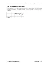
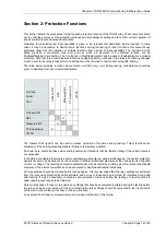
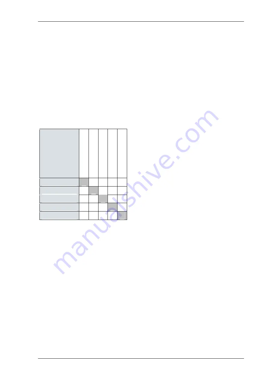
The table below indicates functions where function conflicts may occur during testing, consideration should be
given to disabling functions to avoid interference.
Function
Under
Test
3
-P
h
a
s
e
D
if
f.
R
E
F
M
e
a
s
u
re
d
E
/F
C
T
S
u
p
e
rv
is
io
n
7
4
T
C
S
3-Phase Diff.
O
REF
O
Measured E/F
O
CT Supervision
O
74TCS
The General Pickup LED can be used to assess operation of functions during testing if other functions are
disabled or if the setting allocating General Pickup is temporarily modified.
Particular care should be taken when testing overcurrent functions that the thermal rating of the current inputs is
not exceeded.
It should be considered that where several overlapping elements are used simultaneously, the overall protection
operate time may be dependent on the operation of different individual elements at the various levels of applied
current or voltage. The resulting composite characteristic may be tested by enabling all of the relevant applicable
elements or the element operations can be separated or disabled and tested individually.
All relay settings should be checked before testing begins. It is recommended that the relay settings are extracted
from the relay using ReyDisp Evolution software and a copy of these settings is stored for reference during and
after testing. It may be necessary to disable some protection functions during the testing of other functions to
allow unambiguous results to be obtained.
Care must be taken to reset or re-enable any settings that have been temporarily altered during the testing before
the relay can be put into service. At the end of testing the relay settings should be compared to the file extracted
at the start to ensure that errors have not been introduced.
An example ‘Test Sheet’ summary document is included at the end of this Guide.
Summary of Contents for 7SR23 DAD
Page 1: ...Answers for energy 7SR23 DAD High Impedance Protection Relay Reyrolle Protection Devices ...
Page 2: ......
Page 4: ...7SR23 DAD Contents 2013 Siemens Protection Devices Limited ...
Page 60: ...Chapter 3 7SR23 DAD Performance Specification 2013 Siemens Protection Devices Limited ...
Page 225: ......


