background image

Chapter 2) 7XG3124 Application Guide 

©2014 Siemens Protection Devices Limited  

                                                          Chapter 2 Page 22 of 42 

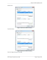
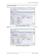
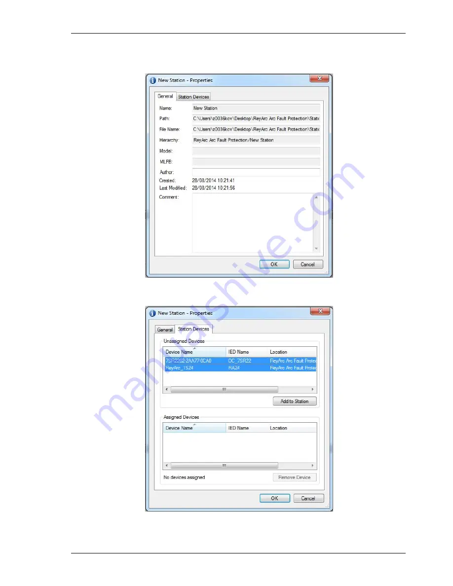
We can give the Station a meaningful name by editing the Item Name. We then nominate the Station 
Devices to be included in the Station by right clicking on the Station and choosing properties. 


Figure 21: Reydisp Manager – Rename IEC61850 Station 

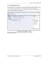
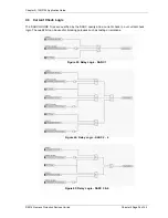
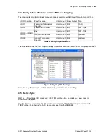
Select Station Devices and you will see a selection of available unassigned IEDs 


Figure 22: Add Device to IEC61850 Station 

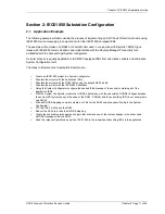
Summary of Contents for 7XG3124 ReyArc24

Page 1: ...Energy Management 7XG3124 ReyArc24 Arc Fault Monitor Relay Reyrolle Protection Devices ...

Page 2: ......

Page 3: ...mission of Siemens Protection Devices Limited nor shall any model or article be reproduced from this document unless Siemens Protection Devices Limited consent While the information and guidance given in this document is believed to be correct no liability shall be accepted for any loss or damage caused by any error or omission whether such error or omission is the result of negligence or any othe...

Page 4: ...7XG3124 Contents Page 2 of 2 2014 Siemens Protection Devices Limited ...

Page 5: ...imited nor shall any model or article be reproduced from this document unless Siemens Protection Devices Limited consent While the information and guidance given in this document is believed to be correct no liability shall be accepted for any loss or damage caused by any error or omission whether such error or omission is the result of negligence or any other cause Any and all such liability is d...

Page 6: ...sions 13 2 4 Custom Labels 14 Section 2 Communication 15 2 1 Physical Connections 15 2 2 IP Addressing 16 Section 3 RA24 File Glossary Firmware Upgrade 17 3 1 RA24 File Glossary 17 3 1 1 1S24 cid 17 3 1 2 sarc exe 17 3 1 3 test exe 17 3 1 4 PIS10 key 17 3 1 5 Autoexec bat 18 3 1 6 CHIP INI 18 3 1 7 HTTP directory 18 3 1 8 ETH1 exe 18 3 1 9 ARC_IO hex 18 3 1 10 SC1x3V0xyy_FULL hex 18 3 2 Upgrading ...

Page 7: ...sor placement for switchgear Busbar coverage External through Hole Detector 9 Figure 11 Sensor placement near Low Voltage Contactor for a Variable Speed Drive 10 Figure 12 Sensor placement for Switchgear cable termination chamber External through Hole Detector 10 Figure 13 Sensor placement for end of Bus chamber External through Hole Detector 11 Figure 14 Sensor placement for Switchgear cable term...

Page 8: ...tion Tables summarise the features available in each model 7 X G 3 1 2 4 0 0 0 A A 0 Arc Fault Protection Category Components Arc Protection 3 1 Device RA24 Arc Fault Monitor 2 4 Network Connection Single port 10Base T 100Base Tx 1 Dual port 10Base T 100Base Tx 100Base Fx 2 Operating Voltage 20 70V DC A 88 300V DC 88 275V AC B Mounting Surface Mount A DIN Rail mount supplied with mounting hardware...

Page 9: ... as a single detector or dual detector package The RA30A single detector version is depicted in figure 1 showing the location of the detection window and the approximate coverage zone Detection window Coverage Zone 3m The recommended spacing for the RA30A single detectors is approximately 5 6 m to ensure adequate detection overlap 5 6 m Figure 2 RA30A single detector Coverage Zone Figure 3 RA30 Sp...

Page 10: ...onal detection window for dual zones of coverage as depicted below Detection windows The recommended spacing for the RA30B single detectors is approximately 5 6 m to ensure adequate detection overlap this combination provides an overall coverage zone of approximately 10 12 m 10 12m 6m Figure 4 RA30B Dual Detector Figure 5 RA30B Dual Detector Spacing ...

Page 11: ...lacement Sensors need to be mounted to provide full coverage of the switchgear cubicles to be protected Where the protected zone is larger than the sensor coverage then the use of multiple sensors is required Precise positioning of the sensors is generally not required as the light caused by the arc is reflected from the walls 2 1 3 Sensor Mounting The RA30 is suitable for flush panel mounting in ...

Page 12: ...emens Protection Devices Limited Chapter 1 Page 8 of 20 2 1 4 Example Sensor Placement The following are some typical examples of sensor placement Figure 7 Sensor placement inside CB racking chamber Figure 8 Sensor placement inside busbar chamber ...

Page 13: ...llation Guide 2014 Siemens Protection Devices Limited Chapter 1 Page 9 of 20 Figure 9 Sensor placement inside cable termination chamber Figure 10 Sensor placement for switchgear Busbar coverage External through Hole Detector ...

Page 14: ...14 Siemens Protection Devices Limited Chapter 1 Page 10 of 20 Figure 11 Sensor placement near Low Voltage Contactor for a Variable Speed Drive Figure 12 Sensor placement for Switchgear cable termination chamber External through Hole Detector ...

Page 15: ...14 Siemens Protection Devices Limited Chapter 1 Page 11 of 20 Figure 13 Sensor placement for end of Bus chamber External through Hole Detector Figure 14 Sensor placement for Switchgear cable termination chamber External through Hole Detector ...

Page 16: ... the RA24 connections The connected sensor inputs need to be enabled and unused inputs disabled via the Web browser configuration tool This is essential to Allow connected sensor inputs to operate for an ARC Fault Allow connected sensor inputs to be supervised Ensure unconnected sensor inputs do not indicate an Arc sensor Alarm condition Figure 15 RA24 Connection Diagram ...

Page 17: ...ted Chapter 1 Page 13 of 20 2 3 Terminal Layout and Module Dimensions Figure 16 Terminal Layout and Module Dimensions The module may be surface mounted or alternatively mounted on a din rail by using 2 optional din rail mounting kits See Catalogue Sheet for Ordering Options ...

Page 18: ...abel identifies the sensor location and the remaining label provides IED identification and IP address details The default labels supplied with the relay may be marked up by hand or alternatively custom labels may be produced using the template provided on the reyrolle website printed and slipped behind the clear windows on the front panel as depicted below Figure 17 RA24 Custom Label ...

Page 19: ...rd Single Port RJ45 10Base T 100Base TX In the single port option the RJ45 port is utilised for connection to an IEC61850 station bus LAN for Goose messaging purposes and for device configuration Figure 19 RA24 RJ45 FO ports Optional Two Port RJ45 10Base T 100Base TX and Fibre 100Base TX The two port option allows one of the ports to connect to an IEC61850 station bus LAN for Goose messaging purpo...

Page 20: ...natively the RA24 or many RA24 Arc Fault Monitors may be connected to a Station Bus Lan as shown below Figure 21 RA24 IEC61850 Station LAN 2 2 IP Addressing The RA24 IED will come preconfigured from the factory with the IP address 192 168 0 220 The default IP address may be used in a web browser session to undertake relay configuration Full details of relay configuration are described in subsequen...

Page 21: ...g into site configuration tools which can add specific Goose to it with whatever VLAN Versioning etc required The Tool can then export a CID file for use on the RA24 Please Note On the RA24 itself it must be called 1S24 cid 3 1 2 sarc exe This file contains the runtime application code for the RA24 arc sensor This executable includes the SystemCorp IEC6180 stack and all the RMS firmware It is usua...

Page 22: ...ication supplied to support the 2nd Ethernet channel On the RA24 this is used for the optic fibre port It is loaded onto A drive using FTP 3 1 9 ARC_IO hex This Intel hex file is used to program the Arc IO expander peripheral on the relay psu board Programming of this file is done using Atmel JTAG or ISP dongles plugged onto the Jtag or ISP headers on the Relay PCB It is not possible to upgrade th...

Page 23: ... they are doing the same thing Connect an Ethernet cable to the RJ45 connector Run CHIPTOOL on PC If necessary configure RA24 to be on same network as PC or configure DHCP Right click on target RA24 and select FTP Copy entire http folder to the RA24 A Edit CHIP INI on PC to set the IP addresses Copy ETH1 exe test exe CHIP INI Autoexec bat 1S24 cid sarc exe to the RA24 A Connect ISP dongle to relay...

Page 24: ...Chapter 1 7XG3124 Installation Guide 2014 Siemens Protection Devices Limited Chapter 1 Page 20 of 20 ...

Page 25: ...imited nor shall any model or article be reproduced from this document unless Siemens Protection Devices Limited consent While the information and guidance given in this document is believed to be correct no liability shall be accepted for any loss or damage caused by any error or omission whether such error or omission is the result of negligence or any other cause Any and all such liability is d...

Page 26: ...location 15 2 7 Creating an IEC61850 Station 15 2 8 PopulatingIEDs In the IEC61850 Project 18 2 9 IEC61850 Station System Configuration 24 2 9 1 System Configuration GOOSEView 27 2 10 CreatingtheRA24 cid File 31 Section 3 Section 6 RA24 IEC61850 Configuration 32 3 1 The CID File 32 Section 4 Section 7 7SR22 Configuration 35 4 1 Logic Configuration 35 4 2 User output Allocation 35 4 3 Current Check...

Page 27: ...ger Rename IEC61850 Station 22 Figure 22 Add Device to IEC61850 Station 22 Figure 23 Add Device to IEC61850 Station 2 23 Figure 24 Add Device to IEC61850 Station 3 23 Figure 25 System Configurator 24 Figure 26 System Configurator Devices 24 Figure 27 System Configurator IP Address 25 Figure 28 System Configurator IP Address 1 25 Figure 29 System Configurator IP Address 2 26 Figure 30 System Config...
Page 28: ...lag Reset 41 Figure 53 RA24 Global Arc Block 41 Figure 55 RA24 Reboot 41 Figure 56 RA24 Reset to Factory Default 41 List of Tables Table 1 RA24 SARC AllocationProtection Zone Tripping 14 Table 2 RA24 Protection Zone Tripping 14 Table 3 RA24 Source Arc Fault Detector Points 15 Table 4 7SR22 Single Point Input GGIO Allocation 15 Table 5 RA24 User Output Allocation 35 Table 6 Binary Output Allocation...

Page 29: ...unication is direct or via a LAN both the PC and the RA24 need to have IP addressing within the same network With a subnet mask of 255 255 255 0 the first 3 octets of the IP address need to be the same for the PC and the RA24 and the last octet needs to be unique for example RA24 IP Address 192 168 0 220 PC IP Address 192 168 0 238 In the above example entering the RA24 IP Address 192 168 0 220 in...

Page 30: ... be prompted for a User name and Password Figure 2 RA24 Login window The factory default username and password is Username admin Password RMS The username and password need only be entered once for each web server session and allows for multiple setting changes with access automatically timing out after 2 minutes of inactivity ...

Page 31: ...2 1 2 Relay Build The Relay Build screen provides device details such as the of the Serial Number and Firmware version The Password may be changed at this point by entering your new password and pressing the Change button enter the user name and previous password if prompted Figure 3 RA24 Homepage ...

Page 32: ...nge the IP address edit the IP address field and then click the Change button and enter the user name and password if prompted Note that the Fibre port must be on a different IP network to the RJ45 port For time stamping in accordance to the IEC61850 standard an SNTP server is required The SNTP server IP address can be set in the IP Configuration screen but if left blank the RA24 will attempt to f...

Page 33: ...will self reset after a 2s delay The trip indication LED is reset either by pressing the front panel reset button via the remote reset status input or via IEC61850 control Trip 1 Yes or No determines if the Sensor input operates the Trip 1 output click on the field to change the state and enter the user name and password if prompted Trip 2 Yes or No determines if the Sensor input operates the Trip...

Page 34: ...Flag The Flag column will indicate and latch for an Arc Sensor operation individual Flags may be reset by clicking on the sensor flag status and entering the user name and password if prompted Count The Count field provides a log of ARC sensor operations since power on or the last counter reset the individual sensor counters may be reset to 0 by clicking on the count field and entering the user na...

Page 35: ...ate an IEC61850 project in a System configurator Populate the project with the Application IEDs Populate the project with the RA24 IEDs using the default RA24 icd file Populate the project with the IEC61850 Substation Using the System Configurator configure the desired IP addressing of the subnet containing all of the application IEDs With the System Configurator create the GOOSE applications with...

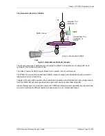
Page 36: ... of the application example is shown in the diagram below TR1 TR1 LT CB Feeder 1A CB Arc Fault coverage is to be provided to the bus circuit breaker chambers and cable termination chambers and shall be current checked with an overcurrent relay Tripping shall be zoned to provide sectionalizing and minimize affected plant Figure 7 Single Line Arc Fault Scheme ...

Page 37: ... initiates the required protection tripping via an Overcurrent Check Tripping in this case will be carried out by hardwiring to respective circuit breakers and using binary outputs from the 7SR22 IED but could also be implemented via Goose by another subscribing IED Flexible tripping logic may be implemented in the 7SR22 according to specific application requirements and may also accommodate diffe...

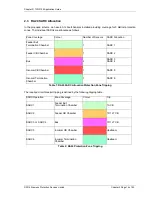
Page 38: ...xit Termination Chamber 1 SARC 1 Feeder CB Chamber 1 SARC 2 Bus 2 SARC 3 SARC 4 Incomer CB Chamber 1 SARC 5 Incomer Termination Chamber 1 SARC 6 Table 1 RA24 SARC AllocationProtection Zone Tripping The required circuit breaker tripping is defined by the following tripping table SARC Operation Zone Coverage Colour Trip SARC 1 Feeder Exit Termination Chamber 1A CB SARC 2 Feeder CB Chamber TR1 LT CB ...

Page 39: ...D and shall assign subscribed SARCs to Single Point Input GGIO as follows Destination 7SR22 Relay Goose Single Point Inputs ARC Fault Detectors Function Single Point Input Description SARC1 CBn CTRL SPi64GGIO1 SPCSO1 CBn Single Point Input 1 SARC2 CBn CTRL SPi64GGIO1 SPCSO2 CBn Single Point Input 2 SARC3 CBn CTRL SPi64GGIO1 SPCSO3 CBn Single Point Input 3 SARC4 CBn CTRL SPi64GGIO1 SPCSO4 CBn Singl...

Page 40: ...e 2014 Siemens Protection Devices Limited Chapter 2 Page 16 of 42 A screenshot of Reydisp Manager is shown below Figure 9 Reydisp Manager Configuration 1 To create a new project choose File and New Figure 10 Reydisp Manager New Project ...

Page 41: ... Protection Devices Limited Chapter 2 Page 17 of 42 Fill in the details including where you want the project file to be stored and hit OK Figure 11 Reydisp Manager New Project 2 The new project has been created Figure 12 Reydisp Manager New Project 3 ...

Page 42: ... our IEDs firstly the Reyrolle 7SR22 Choose Insert and Device and you will be presented with the following screen Figure 13 Reydisp Manager Add Device Select the required relay for this example we will choose a 7SR2202 2AA77 0CA0 ensure that the MLFB code is correctly filled Figure 14 Reydisp Manager Add Device 2 Once the MLFB code is correctly selected you can then select the device ...

Page 43: ...9 of 42 The 7SR22 IED has been added to your project Figure 15 Reydisp Manager Add Device 3 Continue adding Reyrolle IEDs as required using the same process Nominate a meaningful IED name for each IED by right clicking on the IED and choosing properties Figure 16 Reydisp Manager Rename Device ...

Page 44: ...er Rename Device 2 Next we will add the ReyArc RA24 IED which is added as a Third Party ICD File You will need to have the RA24 ICD file Note This file is called 1S24 icd which is available through the Reyrolle website Choose Insert and Third Party ICD File and you will be presented with the following file selection choose the RA24 ICD file Figure 18 Reydisp Manager Insert 3rd Party ICD ...

Page 45: ...24 IED has now been added to your project Figure 19 Reydisp Manager Insert 3rd Party ICD 2 You can nominate a meaningful IED name for the RA24 IED by right clicking on the IED and choosing properties Now we will add a IEC61850 Station choose Insert and Station Figure 20 Reydisp Manager Add IEC61850 Station ...

Page 46: ...ingful name by editing the Item Name We then nominate the Station Devices to be included in the Station by right clicking on the Station and choosing properties Figure 21 Reydisp Manager Rename IEC61850 Station Select Station Devices and you will see a selection of available unassigned IEDs Figure 22 Add Device to IEC61850 Station ...

Page 47: ...de 2014 Siemens Protection Devices Limited Chapter 2 Page 23 of 42 Select the IEDs Figure 23 Add Device to IEC61850 Station 2 Press Add to Station Figure 24 Add Device to IEC61850 Station 3 Press OK to Assign the Devices to the Station ...

Page 48: ...e the IP Addressing for our Station LAN and the Goose Linkages for our Goose messages With the Station highlighted Double Click the System Configurator Button this will start the Digsi System Configurator in the Network view Figure 25 System Configurator Expanding the Station will present the Subnets associated with the Station Figure 26 System Configurator Devices ...

Page 49: ...ubnet will reveal the IP Start address Subnet mask and standard gateway settings Figure 27 System Configurator IP Address We can set the IP start address for our network for convenience in this case 192 168 0 1 The Standard Gateway may also be set at this point if one exists Figure 28 System Configurator IP Address 1 ...

Page 50: ...sly assigned to the Station Figure 29 System Configurator IP Address 2 The individual devices may be selected to set their IP addresses Figure 30 System Configurator IP Address 3 Alternatively at the Subnet level the IP addressing may be automatically allocated starting at the IP start address previously set for the Subnet by pressing the auto IP button ...

Page 51: ... the IP address of each device being incremented and unique Figure 31 System Configurator IP Address 4 2 8 1 System Configuration GOOSE View With the network addressing having been completed we ll now create our GOOSE applications and associated GOOSE linkages The screenshot below shows the GOOSE view within the ReyArc System configurator Station Figure 32 System Configurator GOOSE ...

Page 52: ...f 42 A GOOSE application needs to be added to you station Select New Station Add New Goose Application Figure 33 System Configurator GOOSE 2 Once our Goose application is added selecting this application reveals the associated IEDs as sources and destintions Figure 34 System Configurator GOOSE 3 ...

Page 53: ...tinations windows will show the Logical Nodes and their associated Data Objects Firstly we ll select the RA24 IED and expand RMS_SARC1 and choose FADet to Add as a Source Figure 35 System Configurator GOOSE 4 Once Added as a source it will appear in the interconnections In turn add all of the required source SARCs Figure 36 System Configurator GOOSE 5 ...

Page 54: ...ion Devices Limited Chapter 2 Page 30 of 42 The SARCs are linked to the respective 7SR22 IED Single Point Input GGIO chosen from the Destinations window Figure 37 System Configurator GOOSE 6 With the links complete save and exit the Digsi System Configurator ...

Page 55: ... IED Configuration process Note Please close and re open Digsi System configurator before proceeding with the next step 1 Open the Station in Reydisp Manager go to the Network screen select the RA24 IED right click and select Export IEC61850 device configuration Figure 38 System Configurator CID File Save the file for later RA24 configuration System configuration is now complete Save the file as 1...

Page 56: ...t Configuration is contained in the cid file for the RA24 created earlier from our Substation configuration process example and needs to be loaded into the RA24 IED FTP 1S24 cidFile We will be using the Beck s CHIPTOOL software utility to establish a terminal session with the RA24 and to FTP the cid file Download CHIPTOOL for free from http www beck ipc com en download licence asp id chiptool_inst...

Page 57: ...osing Tools and FTP Client Figure 40 CHIPTOOL Connect Enter the following Username and Password for the FTP session User ftp Password ftp Figure 41 CHIPTOOL FTP You will be presented with 2 file directories the left side is the source directory and the right side A is the RA24 Locate and select the saved 1S24 cid file created earlier right click on the file and copy it to the A drive ...

Page 58: ...in the A drive right click and ensure it is renamed as 1S24 cid Note The new cid file must be renamed 1S24 cid Figure 42 CHIPTOOL FTP 2 Rebooting The RA24With The New 1S24 cid File A reboot of the RA24 is required once the new 1S24 cid file has been loaded The reboot can be done either via powering down and repowering the device or by pressing and holding the Flag Reset button for about 5 sec unti...

Page 59: ...ions outline the logic implemented 4 2 User output Allocation Using the previously defined ARC Fault Sensor Zones we will nominate the User Outputs that will capture the resultant SARC operation and current check logic Zone Coverage Colour SARC Allocation User Output Feeder Exit Termination Chamber SARC 1 User Output 1 Feeder CB Chamber SARC 2 User Output 2 Bus SARC 3 SARC 4 User Output 2 Incomer ...

Page 60: ...42 4 3 Current Check Logic The SARC GOOSE Trips are qualified by the SARC quality and a current check in our current check logic The quality bit can be used for blocking purposes such as testing or isolations Figure 43 Relay Logic SARC 1 Figure 44 Relay Logic SARC 2 4 Figure 45 Relay Logic SARC 5 6 ...

Page 61: ... 2 BO3 TR1 LT CB SARC 5 Incomer CB Chamber User Output 3 BO4 Upstream SARC 6 Incomer Termination Chamber User Output 3 BO4 Upstream Table 6 Binary Output Allocation The screenshot shows the User Output to Binary Output allocation in the setting editor of Reydisp Manager Figure 46 Reydisp Relay Settings Complete any other Protection settings otherwise required and save your setting 4 5 Device Sync ...

Page 62: ...cations provided on the front of the Arc Fault Monitor Figure 47 RA24 Front Layout View 5 2 Power Up When powering up all the Leds will flash once and then extinguish and then in turn sequentially illuminate 1 led at a time until all Leds are illuminated the sequence takes about 14 secs during the boot cycle When the boot cycle is complete the RA24 will indicate the current state ...

Page 63: ...ommunications failure 5 3 System Status Auxiliary Supply or Relay Healthy Indication Refer to the Commissioning section Interpreting Vx Auxiliary Supply or Relay Healthy Indications for further details Ethernet Activity Figure 48 RA24 System Status 5 4 Service Alarm The module self supervision checks the following Auxiliary supply failure Internal supply rail is outside acceptable limits CPU Hardw...

Page 64: ...upervision Indicates solid when an Arc Sensor has faulted either due to an open circuit sustained short circuit 10 sec or high ambient lighting Sensor Alarm The affected sensor will be indicated by its front panel sensor LED 1 16 flashing The Sensor Alarm will self reset upon the fault conditions being corrected 5 7 Arc Trip Indicates solid when the respective assigned self reset Arc Trip contacts...

Page 65: ...continue to flash for approx 9 secs and then extinguish and then in turn sequentially illuminate 1 led at a time until all Leds are illuminated the sequence takes another 14 secs approx The reboot must be used after loading in new icd files into the IED and restarting the software process with the new 61850 configurations The reboot may also be required if for some reason the RA24 does not respond...

Page 66: ...Chapter 2 7XG3124 Application Guide 2014 Siemens Protection Devices Limited Chapter 2 Page 42 of 42 ...

Page 67: ...d nor shall any model or article be reproduced from this document unless Siemens Protection Devices Limited consent While the information and guidance given in this document is believed to be correct no liability shall be accepted for any loss or damage caused by any error or omission whether such error or omission is the result of negligence or any other cause Any and all such liability is discla...

Page 68: ...n Trouble Shooting 6 2 7 ARC Trip Trouble Shooting 6 Section 3 Commissioning Ethernet Communications 7 3 1 General Ethernet Communications Trouble Shooting 7 3 2 IEC61850 GOOSE Message Trouble Shooting 7 Section 4 RA24 Power Supply Indications 8 4 1 Interpreting Vx Auxiliary Supply or Relay Healthy Indications 8 List of Tables Table 1 System Power Up 4 Table 2 Sensoe Failure Alarm Verification 5 T...

Page 69: ...ion are correct 1 2 Insulation The relay and its associated wiring may be insulation tested between all electrically isolated circuits all circuits and earth An electronic or brushless insulation tester should be used having a dc voltage not exceeding 1000V Accessible terminals of the same circuit should first be strapped together Deliberate circuit earthing links removed for the tests subsequentl...

Page 70: ...the protection design schematic connected to a Substation LAN and confirm all IEC61850 configurations 7 Confirm Fail alarm relay is closed Terminals 25 and 26 8 Apply correct Auxiliary voltage to power up the RA24 9 Upon power up the relay enters a relay boot cycle all the Leds will flash once and then extinguish and then in turn sequentially illuminate 1 led at a time until all Leds are illuminat...

Page 71: ...put 8 Confirm the associated sensor Fail indications clear and the Relay Fail Alarm output contact opens Table 2 Sensor Failure Alarm Verification 2 3 Arc Trip Testing Item Description Complete 1 Initiate the operation of each sensor by the use of a suitably powered camera flash If a current check interlock is employed in your ARC Fault protection scheme ensure that current is injected into the as...

Page 72: ...r inputs and check that all Sensor Alarm indications are extinguished Table 5 Sensor Failure Alarm 2 6 ARC Sensor Supervision Trouble Shooting Item Description Complete 1 If there is a Sensor Alarm indication re check the RA30 wiring integrity 2 Check that the sensors are connected to the correct arc sensor inputs and check that the correct sensor inputs are enabled and unused inputs are disabled ...

Page 73: ...age Trouble Shooting If a SARC GOOSE is not being received by a subscribing IED check the following Item Description Complete 1 Check that the required SARC is enabled in the RA24 2 For a current check scheme is the current check element enabled and being picked up 3 Check the GOOSE linkages in the Substation Project and ensure that the correct sources and subscriptions have been established 4 Che...

Page 74: ...eck SNTP server is functioning or check that the SNTP Server address on the IP config screen is correct Off Internal RA24 Communications failure A permanent Internal RA24 Communications failure will assert the Service Alarm Section 4 RA24 Power Supply Indications 4 1 Interpreting Vx Auxiliary Supply or Relay Healthy Indications The Healthy LED will be illuminated solid to indicate normal operation...

Page 75: ......

Page 76: ...h Farm Road Hebburn Tyne Wear NE31 1TZ United Kingdom Phone 44 0 191 401 7901 Fax 44 0 191 401 5575 E mail marketing spdl gb siemens com For enquires please contact our Customer Support Center Phone 49 180 524 8437 24hrs Fax 49 180 524 24 71 E mail support ic siemens com EMEA T10041 00 76GB September 2014 ...

Reviews: