Chapter 2) 7XG3124 Application Guide
©2014 Siemens Protection Devices Limited Chapter 2 Page 35 of 42
Section 4: 7SR22 Configuration
4.1 Logic Configuration
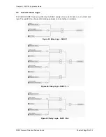
Our application is to employ a current check using the pickup of an Instantaneous Overcurrent Element (50-
1) to qualify an Arc Sensor operation. The following sections outline the logic implemented.
4.2 User output Allocation
Using the previously defined ARC Fault Sensor Zones we will nominate the User Outputs that will capture
the resultant SARC operation and current check logic.
Zone Coverage
Colour
SARC Allocation
User Output
Feeder Exit
Termination Chamber
SARC 1
User Output 1
Feeder CB Chamber
SARC 2
User Output 2
Bus
SARC 3
SARC 4
User Output 2
Incomer CB Chamber
SARC 5
User Output 3
Incomer Termination
Chamber
SARC 6
User Output 3
Table 5: RA24 User Output Allocation


