background image

English

7XT3300-0*A00

36

C53000-B1175-C129-1

Control module C53207-A332-B2-, 7XT3300-0*A00/DD and higher

Figure 4 Control module with location of the jumper

S1

H102

H103

X 401
X 402

88 V (Default setting )

19 V

X 403

STBG
C53207-A332-B2-

Summary of Contents for 7XT3300-0 A00 Series

Page 1: ...r de la version matériel DD device version DD and higher Copyright Siemens SA 2011 Manuel Manual Order No C53000 B1175 C129 1 Mode d emploi Français Page 3 Générateur 20 Hz Directions for Use English Page 27 20 Hz Generator ...

Page 2: ... à partir de 7XT3300 0 A00 DD Rear side of 20 Hz Generator device version 7XT3300 0 A00 DD and higher Inscription sur la face arrière du générateur 20 Hz à partir de 7XT3300 0 A00 EE Imprint on the rear side of 20 Hz Generator device version 7XT3300 0 A00 EE and higher ...

Page 3: ...ballage et emballage de l appareil 6 Stockage et transport 6 Utilisation 7 Description fonctionnelle 7 Cavalier et fusibles sur circuits imprimés 11 Dimensions 13 Consignes de raccordement 15 Données techniques 17 Schéma général 23 Exemples de raccordement 24 Informations pour la commande 25 Description des modifications 26 ...

Page 4: ... et fabriqué pour être utilisé dans un environnement industriel Le produit est conforme à la norme internationale de la série IEC 60255 et à la disposition nationale VDE 0435 Consignes et Avertissements Les consignes et avertissements suivants seront utilisés dans ce mode d emploi pour votre sécurité et pour garantir la durée de vie de l appareil Les signalisations et définitions de standards suiv...

Page 5: ... qui connaît et suit les dispositions de sécurité et les mesures de précaution Vous ne devez jamais entreprendre les travaux en présence de tensions dangereuses Mettez l appareil hors tension Le transport stockage installation et montage de l appareil effectués d après les consignes et avertissements de ce manuel d instructions ainsi que l utilisation et l entretien appropriés sont les garants d u...

Page 6: ...areils sont à inspecter visuellement pour s assurer de leur parfait état mécanique Veuillez respecter aussi les consignes quand celles ci sont ajoutées à l appareil Avant de mettre l appareil sous tension pour la première fois ou après un stockage il est conseillé de le laisser dans son environnement de fonctionnement définitif pendant au moins 2 heures afin qu il atteigne son équilibre thermique ...

Page 7: ...n transformateur La mesure n est pas influencée par le mode de fonctionnement du générateur et permet ainsi une mesure à l arrêt du générateur Description fonctionnelle Principe fondamental Via le 7XT33 une tension d un maximum de 1 de la tension du générateur est appliquée au point neutre En cas de défaut à la terre au point neutre du générateur un courant va circuler à travers la résistance de d...

Page 8: ...e est déconnectée si une surcharge est détectée Dans ce cas le relais de signalisation retombe Position de repos et la BLOCKED LED rouge s allume L appareil tente un redémarrage après un temps d attente d env 60 s Au cours du redémarrage la BLOCKED LED rouge clignote Si le défaut persiste la BLOCKED LED rouge s allume et après un temps d attente le redémarrage s effectue à nouveau Ce processus se ...

Page 9: ...tatut Relais de signalisation Sortie Signal 20 Hz HORS SERVICE EN SERVICE Appareil prêt à être mis en service activé Oui EN SERVICE HORS SERVICE Appareil pas prêt à être mis en service ou bloqué via entrée binaire désactivé Non HORS SERVICE Clignote ment Tension auxiliaire 80 V désactivé Non Clignotement HORS SERVICE Redémarrage désactivé Non HORS SERVICE HORS SERVICE Appareil hors service désacti...

Page 10: ...sommation de courant excité approx DC 1 8 mA indépendamment de la tension d activation Seuil de commutation Commutable avec cavalier S1 cf figure 4 Pour tensions de commande DC 24 V DC 48 V DC 60 V Uhigh DC 19 V Ulow DC 10 V Pour tensions de commande DC 110 V DC 125 V DC 220 V DC 250 V Uhigh DC 88 V Ulow DC 44 V Tension maximale autorisée DC 300 V Suppression d impulsion d entrée Le signal doit ap...

Page 11: ...00 Français C53000 B1175 C129 1 11 Cavalier et fusibles sur circuits imprimés Module de partie du réseau C53207 A332 B12 à partir de 7XT3300 0 A00 DD Figure 3 Module de partie du réseau avec situation des fusibles ...

Page 12: ...Français 7XT3300 0 A00 12 C53000 B1175 C129 1 Module de commande C53207 A332 B2 à partir de 7XT3300 0 A00 DD Figure 4 Cavalier sur le module de commande C53207 A332 B2 ...

Page 13: ...7XT3300 0 A00 Français C53000 B1175 C129 1 13 Dimensions Boîtier 7XT33 pour la version de montage en saillie Figure 5 Boîtier 7XT33 dans la version de montage en saillie ...

Page 14: ...ais 7XT3300 0 A00 14 C53000 B1175 C129 1 Boîtier 7XT33 pour le montage encastré dans un tableau ou dans une armoire Figure 6 Dimensionnement pour montage encastré du 7XT33 dans un tableau ou dans une armoire ...

Page 15: ...ornier de connexion à 12 pôles Tableau 4 Rampe de connexion REMARQUE En raison de compatibilité électromagnétique vous devez torsader les 2 fils de connexion entre le 7XT33 Bornes 11 12 et le 7XT34 Borne 1B4 cf figure 10 avec 20 tours m Une fois torsadés la longueur ne doit pas dépasser 35 cm Connexion Désignation 1 Tension auxiliaire L1 UH 2 Tension auxiliaire L2 UH 3 Tension auxiliaire L3 4 Mise...

Page 16: ...de câble à la sortie 11 12 doit être de 2 5 mm2 Utiliser uniquement des conducteurs en cuivre Nous recommandons les cosses de la série PIDG de l entreprise Tyco Electronics AMP par exemple Cosse à anneau PIDG PN 320565 0 Cosse à fourche PIDG PN 321233 0 Connexion directe Conducteur massif ou conducteur torsadé avec manchon pour torons pour les sections de câbles de 0 5 mm2 à 2 6 mm2 soit AWG 20 à ...

Page 17: ... action pour RL 8 Ω env 76 Tension auxiliaire continue nominale DC 110 V à DC 220 V Plage de tension autorisée DC 88 V à DC 250 V Tension auxiliaire alternative nominale triphasée triphasée 3 x AC 100 V à AC 120 V Tension auxiliaire alternative nominale monophasée AC 100 V à AC 120 V Plage de tension autorisée AC 88 V à AC 230 V Temps de maintien en cas de panne de la tension auxiliaire DC 110 V c...

Page 18: ...50 V DC 88 V Uhigh DC 88 V Ulow DC 44 V Tension autorisée en continu DC 300 V Relais de signalisation Connexions 5 7 et 9 Puissance de coupure EN SERVICE 30 W VA HORS SERVICE 20 VA 30 W ohmique 25 W pour L R 50 ms Tension de coupure DC 24 V à DC 250 V AC 24 V à AC 230 V Courant autorisé 1 A en continu Températures ambiantes admissibles pour RL 5 Ω 55 C pour RL 5 Ω 70 C REMARQUE RL détermine la rés...

Page 19: ...VDE 0435 Partie 301DIN VDE 0435 110 Contrôle de haute fréquence CEI 60255 22 1 Classe III et VDE 0435 Partie 303 Classe III 2 5 kV crête 1 MHz τ 15 μs 400 impulsions à la s durée de contrôle 2 s Ri 200 Ω Décharge d électricité statique CEI 60255 22 2 Classe IV et CEI 61000 4 2 Classe IV 8 kV décharge par contact 15 kV décharge dans l air deux polarités 150 pF Ri 330 Ω Exposition au champ HF balaya...

Page 20: ...à fréquence industrielle CEI 60255 6 CEI 61000 4 8 Classe IV 0 5 mT 50 Hz 30 A m en permanence 300 A m pendant 3 s 50 Hz Insensibilité aux chocs oscillatoires Oscillatory Surge Withstand Capability IEEE Std C37 90 1 2 5 kV crête 1 MHz τ 15 μs 400 impulsions à la s durée de contrôle 2 s Ri 200 Ω Transitoires rapides salve avec couplage capacitif IEEE Std C37 90 1 4 kV 5 ns 50 ns 5 kHz longueur de B...

Page 21: ... CEI 60255 21 3 Classe 1 CEI 60068 3 3 Sinusoïdal 1 Hz à 8 Hz 3 5 mm Amplitude axe horizontal 1 Hz à 8 Hz 1 5 mm Amplitude axe vertical 8 Hz à 35 Hz 1 g accélération axe horizontal 8 Hz à 35 Hz 0 5 g accélération axe vertical Balayage de fréquence 1 Octave min 1 cycle selon 3 axes orthogonaux Normes CEI 60255 21 et CEI 60068 Oscillation CEI 60255 21 1 Classe 2 CEI 60068 2 6 Sinusoïdal 5 Hz à 8 Hz ...

Page 22: ...d humidité relative pendant 56 jours par an éviter la condensation en service Siemens recommande de placer les appareils de façon à ne pas les exposer au rayonnement solaire direct afin d éviter les grandes fluctuations de température qui pourraient provoquer le phénomène de condensation Dimensions cf figures 5 et 6 Poids env 6 1 kg Type de protection selon EN 60529 IP20 REMARQUE L appareil connaî...

Page 23: ...7XT3300 0 A00 Français C53000 B1175 C129 1 23 Schéma général Figure 8 Schéma général 7XT3300 0 A00 ...

Page 24: ...on DC via un fusible automatique 2 A Figure 10 Raccordement de la protection de défaut terre du stator à 100 avec le transformateur de point neutre ou de mise à la terre REMARQUE Pour un fonctionnement correcte de la protection 20 Hz la résistance de charge doit être RL 0 5 Ω UH UH 1 2 1 3 2 A 2 4 5SY5202 7 7XT33 ...

Page 25: ...emens Fusible 4AT Schurter 5 mm x 20 mm 0001 2510 Fusible 4AT Siba 5 mm x 20 mm 179200 4A Fusible 4AT SOC 5 mm x 20 mm SHV12 4A Fusible 5AT Schurter OMK 125 3404 2317 11 Fusible 5AT Littelfuse Série 154 154 005 Filtre passe bande 20 Hz 7XT34 Siemens 7XT3300 0 A00 Rail de montage dans rack 19 2 pièces C73165 A63 D200 1 AVERTISSEMENT Fusible incorrect Le non respect des consignes peut entraîner de g...

Page 26: ...e Borne SIPROTEC 4 à 12 pôles Attention Les connexions ont été modifiées 7XT3300 0BA00 DE 7XT3300 0CA00 DE Traitement de l entrée binaire Problème Pour le statut du matériel DD une tension 20 Hz peut apparaître à la sortie temporairement malgré l activation de l entrée binaire 7XT3300 0BA00 EE 7XT3300 0CA00 EE Augmentation de la tension de sortie de 26 V Introduction de nouveaux fusibles pour perm...

Page 27: ...s and Warnings 28 Unpacking and Re packing 30 Storage and Transport 30 Application 31 Function Description 31 Jumper and Fuses on the Printed Circuit Boards 35 Dimensions 37 Installation Hints 39 Technical Data 41 General Diagram 47 Connection Examples 48 Order Information 49 History 50 ...

Page 28: ... standards EN 60255 6 for low voltage directive by Siemens AG The device is designed and manufactured for application in industrial environment The product conforms with the international standards of IEC 60255 and the German standards VDE 0435 Notes and Warnings The warnings and notes contained in this booklet serve for your own safety and for an appropriate lifetime of the device Please observe ...

Page 29: ...trained personnel who are familiar with and observe the safety requirements and precautions Work may never be carried out if there is any dangerous voltage present Deenergize the device The successful and safe operation of this device is dependent on proper transport and storage proper handling installation operation and maintenance by qualified personnel under observance of all warnings and hints...

Page 30: ...d to ensure that there are no external traces of damage Please observe absolutely all notes and hints which may be enclosed in the packaging Before initial energization with supply voltage or after storage the device shall be situated in the operating area for at least two hours in order to ensure temperature equalization and to avoid humidity influences and condensation For further transport the ...

Page 31: ...s in all windings including the machine starpoint The measuring principle used is not influenced at all by the generator s operation and allows measurements even with the generator at standstill Function Description Basic Principle The 7XT33 injects into the generator starpoint a voltage of max 1 of the rated generator voltage If an earth fault occurs in the generator starpoint the 20 Hz voltage d...

Page 32: ...he output the internal device voltage is overloaded the 7XT33 will be protected by turning off the output module The signal relay drops out idle state and the red BLOCKED LED lights up After a delay of approx 60 s the device attempts to restart The red BLOCKED LED keeps flashing during the restart If the fault has not been eliminated the red BLOCKED LED lights up and the device attempts to restart...

Page 33: ...reen RUN Description Condition of signal relay Output of 20 Hz signal OFF ON Device is ready for operation picked up Yes ON OFF Device is not ready for opera tion or blocked via binary input dropped out No OFF Flashing Auxiliary voltage 80 V dropped out No Flashing OFF Restart dropped out No OFF OFF Device is off dropped out No NOTE The shining of the red BLOCKED LED means no 20 Hz voltage availab...

Page 34: ...rent consumption energized approx DC 1 8 mA independent of control voltage Pick up thresholds selectable with jumper S1 see figure 4 for control voltages DC 24 V DC 48 V DC 60 V Uhigh DC 19 V Ulow DC 10 V for control voltages DC 110 V DC 125 V DC 220 V DC 250 V Uhigh DC 88 V Ulow DC 44 V Maximum permissible voltage DC 300 V Impulse filter on input Signal must be provided 500 ms Table 3 Jumper S1 F...

Page 35: ...4A c SOC SHV12 4A Fusible cut out insert 5AT a Schurter OMK 125 3404 2317 11 b Littelfuse Series 154 154 005 Warning Replace the fuse only by the original type because the holders are designed for this type only NZT C53207 A332 B12 The fusible link inserts must be replaced only by the types mentioned If other types are used the parameters and properties given for the device no longer apply Warning...

Page 36: ...00 0 A00 36 C53000 B1175 C129 1 Control module C53207 A332 B2 7XT3300 0 A00 DD and higher Figure 4 Control module with location of the jumper S1 H102 H103 X401 X402 88 V Default setting 19 V X403 STBG C53207 A332 B2 ...

Page 37: ...of 7XT33 surface mounting version 209 5 8 23 34 1 34 266 10 47 244 9 60 Side View Mounting Holes of Mounting Plate Rear View 200 0 3 7 87 0 01 12 5 0 49 6 4 0 25 300 0 3 11 81 0 01 225 8 86 220 8 66 100 0 3 3 93 0 01 312 8 12 28 Ø4 5 0 16 or M5 RUN B LOCK E D Mounting Plate Dimensions in mm Values in Brackets in Inches ...

Page 38: ...ounting or cubical installation resp Ø6 0 24 172 6 77 29 5 1 16 34 1 34 266 10 47 244 9 60 Side View resp Ø5 0 20 or M4 Panel cut out Front View 180 0 5 7 09 0 02 7 3 0 29 13 2 0 52 5 4 245 1 9 65 0 04 255 8 0 3 10 07 0 01 221 2 8 70 0 08 220 8 66 225 8 86 206 5 0 3 8 13 0 01 Mounting Plate B LOCK E D RUN Dimensions in mm Values in Brackets in Inches ...

Page 39: ...elivery Figure 7 Screw type terminals on the 12 pin terminal block Table 4 Terminal block NOTE For electromagnetic compatibility reasons you must twist the line pair with about 20 turns between the 7XT33 clamps 11 12 and the 7XT34 clamp 1B4 see Figure 10 The line must not be longer than 35 cm in the twisted condition Connector Designation 1 Auxiliary voltage L1 UH 2 Auxiliary voltage L2 UH 3 Auxil...

Page 40: ...on outputs 11 12 must be 2 5 mm2 Use copper conductors only Recommended cable lugs series PIDG of Messrs Tyco Electronics AMP e g ring type cable lug PIDG PN 320565 0 fork type cable lug PIDG PN 321233 0 Direct connection with solid bare wire or flexible wire with end sleeves for cross section from 0 5 mm2 to 2 6 mm2 AWG 20 to AWG 14 When using one single conductor the conductor end must be insert...

Page 41: ...oltage ranges Efficiency with RL 8 Ω approx 76 Nominal auxiliary DC voltage DC 110 V to DC 220 V Permissible DC voltage range DC 88 V to DC 250 V Nominal auxiliary AC voltage 3 phase 3 x AC 100 V to AC 120 V Nominal auxiliary AC voltage single phase AC 100 V to AC 120 V Permissible DC voltage range AC 88 V to AC 230 V Bridging time for failure auxiliary voltage DC 110 V short circuit 50 ms with ra...

Page 42: ...0 V DC 250 V DC 88 V Uhigh DC 88 V Ulow DC 44 V Permissible voltage continuous DC 300 V Signal relay Terminal points 5 7 and 9 Switching capacity MAKE 30 W VA BREAK 20 VA 30 W resistance load 25 W at L R 50 ms Switching voltage DC 24 V to DC 250 V AC 24 V to AC 230 V Permissible current 1 A permanent Permissible Ambient Temperatures with RL 5 Ω 55 C or 131 F with RL 5 Ω 70 C or 158 F NOTE RL descr...

Page 43: ... 2 5 kV peak value 1 MHz τ 15 μs 400 pulses per s test duration 2 s Ri 200 Ω Electrostatic Discharge IEC 60255 22 2 Class IV and IEC 61000 4 2 Class IV 8 kV contact discharge 15 kV air discharge both polarities 150 pF Ri 330 Ω Irradiation with HF Field Frequency Sweep IEC 60255 22 3 Class III IEC 61000 4 3 Class III 10 V m 80 MHz to 1000 MHz 80 AM 1 kHz 10 V m 800 MHz to 960 MHz 80 AM 1 kHz 10 V m...

Page 44: ... continuous 300 A m for 3 s 50 Hz Oscillatory Surge Withstand Capability IEEE Std C37 90 1 2 5 kV peak value 1 MHz τ 15 μs 400 pulses per s test duration 2 s Ri 200 Ω Fast Transient Surge Withstand Cap IEEE Std C37 90 1 4 kV 5 ns 50 ns 5 kHz burst length 15 ms repetition rate 300 ms both polarities Ri 50 Ω test duration 1 min Radiated Electromagnetic Interference IEEE Std C37 90 2 35 V m 80 MHz to...

Page 45: ...60068 3 3 sinusoidal 1 Hz to 8 Hz 3 5 mm amplitude horizontal axis 1 Hz to 8 Hz 1 5 mm amplitude vertical axis 8 Hz to 35 Hz 1 g acceleration horizontal axis 8 Hz to 35 Hz 0 5 g acceleration vertical axis Frequency sweep 1 octave min 1 cycle in 3 orthogonal axes Standards IEC 60255 21 and IEC 60068 Vibration IEC 60255 21 1 Class 2 IEC 60068 2 6 sinusoidal 5 Hz to 8 Hz 7 5 mm amplitude 8 Hz to 150 ...

Page 46: ...ative humidity on 56 days of the year up to 93 relative humidity Condensation must be avoided in operation All devices shall be installed such that they are not exposed to direct sunlight nor subject to large fluctuations in temperature that may cause condensation Dimensions See figures 5 and 6 Mass Approx 6 1 kg Degree of protection according to EN 60529 IP20 NOTE With maximum power output the de...

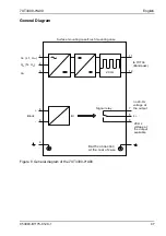
Page 47: ...ral diagram of the 7XT3300 0 A00 20 Hz no 20 Hz voltage at the output 20 Hz voltage at the output available L Block BI 6 8 7 5 9 11 12 to 7XT34 Bandpass UL1 L1 UH UL2 N UH UL3 1 2 3 Surface mounting case Flush mounting case Signal relay 4 Earth connection at the rear of case ...

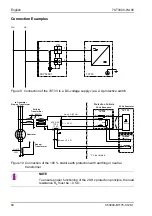
Page 48: ...nctioning of the 20 Hz protection principle the load resistance RL must be 0 5 Ω UH UH 1 2 1 3 2 A 2 4 5SY5202 7 7XT33 7XT34 7XT33 7UM62 Protection Cubicle 20 Hz Bandpass 20 Hz Generator max 3 A 20 Hz Burden 0 5 Ω 400 A 5 A 1FS5 15 VA 1 A1 1A4 1B 1 1B4 11 12 R13 R14 J8 J7 P1 P2 S2 S1 UE IEE1 RL 0 5 Ω 1A2 1A 3 330 Ω 660 Ω 660 Ω UNG 3 500 V 20 Hz UN 3 a b Neutral Transformer 500 V 3 Earthing Transfo...

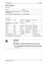
Page 49: ...2 7 Siemens Fuse 4AT Schurter 5 mm x 20 mm 0001 2510 Fuse 4AT Siba 5 mm x 20 mm 179200 4A Fuse 4AT SOC 5 mm x 20 mm SHV12 4A Fuse 5AT Schurter OMK 125 3404 2317 11 Fuse 5AT Littelfuse Series 154 154 005 20 Hz Bandpass 7XT34 Siemens 7XT3400 0 A00 Mounting rail for 19 racks 2 pieces C73165 A63 D200 1 WARNING Wrong fuse Non observance may lead to death or serious injury Only the given fusible cut out...

Page 50: ...s have changed their function 7XT3300 0BA00 DE 7XT3300 0CA00 DE Changing binary input problem device version DD can produce a 20 Hz voltage temporarily while disable it with activate binary input 7XT3300 0BA00 EE 7XT3300 0CA00 EE Increase 20 Hz voltage below load to 26 V New fuses for operation with permanent auxiliary voltage AC 230 V Correction of legend for front and backside 7XT3300 0BA00 FF 7...

Page 51: ...7XT3300 0 A00 C53000 B1175 C129 1 51 ...

Page 52: ...r au versement de dommages et intérêts Tous nos droits sont réservés notamment pour le cas de la délivrance d un brevet ou celui de l enregistrement d un modèle d utilité publique Copying this document and giving it to others and the use or communication of the contents thereof are forbidden without express authority Offenders are liable to the pay ment of damages All Rights are reserved in the ev...

Reviews: