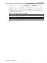
Synchronizing more than 20 SIPROTEC 3 Devices
Here, the use case presented in chapter
3.4 Synchronizing more than 12 SIPROTEC 4 or SIPROTEC 5 Devices
expanded with additional SIPROTEC 3 devices. The minute pulse arriving at R1 is, in this case, also decoupled
by way of the electronic load disconnecting relay (K2) and forwarded to the protection devices.
i
i
NOTE
In this application, the battery of the plant that you connect to the contacts marked L+ and L- must be
integrated (connected in series to the switch of the electronic load disconnecting relay K2). Set the switch
threshold values for the binary inputs on the SIPROTEC 3 devices according to the battery voltage of the
plant.
Table 3-5
DIP Switch Positions in the Sync-Transceiver
Switch
Position
S1/1
Application-specific (light idle state mode as per the system configuration at the optical-fiber
input R1)
S1/2
Open
S1/3
Closed (channel pairing mode)
S1/4
Closed (K2 is activated)
3.6
Application Examples
3.6 Synchronizing more than 20 SIPROTEC 3 Devices
Accessories, Sync Transceiver, Optical/Electrical Converter for Time Synchronization, Manual
31
C53000-G9050-C168-1, Edition 09.2019


