Device Connections
Arrangement of the Connections
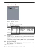
[sc_7XV5654_device, 1, --_--]
Figure 2-2
Sync Transceiver Front View
Connections X2, X7, X1
Connection
Meaning
Description
X2
Auxiliary voltage
DC: L+/AC: L1
DC: L-/AC: N
X7
Fault-signaling connection M1
2, 1
X1
2 electrical 24-V outputs on one socket with 9‑pole D-sub connector plug
PE conductor terminal, IEC 60417-5019
Optical Fiber Connectors R1 and R2
Connection
Meaning
R1 and R2
Optical fiber receiver (ST bayonet closure)
R1 and R2 are the receiving optical fiber connectors of the Sync-Transceiver (refer to
The optical interfaces are set to use positive logic (light idle state: OFF) at the factory. Switched-on light is
treated as active = 1 (high). To adapt to systems that use negative logic, a switch is integrated in each input
channel R1 and R2. If you set the DIP switches 1/2 to ON, you switch to negative logic.
2.2
2.2.1
Device Structure
2.2 Device Connections
16
Accessories, Sync Transceiver, Optical/Electrical Converter for Time Synchronization, Manual
C53000-G9050-C168-1, Edition 09.2019

