!
DANGER
High touch voltages.
Noncompliance leads to death or severe injury.
²
Work may only be carried out by electrically qualified personnel who are familiar with and observe the
safety requirements and precautions.
²
Never perform any work in the presence of hazardous voltages.
²
Completely de-energize the plant (control cabinet, switch panel) where the device is to be operated
during connection work.
²
Take measures to protect against electrostatic discharge. Do not touch any other electrical compo-
nents apart from the jumper.
²
The jumpers may only be set by electrically qualified personnel possessing knowledge about handling
MOS technology circuits.
To change the jumper positions, perform the following work steps:
²
Remove the cover from the housing.
²
To do this, carefully press the catches into the inside of the device using a small screwdriver.
²
Set the jumper to the desired position, refer to
²
Snap the device cover in place.
Switch Positions
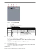
All DIP switches can be operated from outside the housing.
For the standard application, the DIP switches are set at the factory as follows and the device can be used
immediately:
•
All optical fiber receivers: Light idle state OFF
•
Operating mode: 2-channel
•
Electronic load disconnecting relay: Inactive
2.2.2.3
Device Structure
2.2 Device Connections
18
Accessories, Sync Transceiver, Optical/Electrical Converter for Time Synchronization, Manual
C53000-G9050-C168-1, Edition 09.2019

