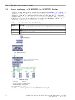
Synchronizing up to 20 SIPROTEC 3 Devices
In this application example, the hardware configuration is nearly identical to that in chapter
more than 12 SIPROTEC 4 or SIPROTEC 5 Devices
. At 20 (2 × 10), only the number of protection devices that
can be connected is higher because the SIPROTEC 3 inputs put less of a load on the Sync-Transceiver switching
output. SIPROTEC 3 devices do not have a separate time-synchronization input. Instead, they use the binary
inputs for this. In addition, SIPROTEC 3 devices, in contrast to SIPROTEC 4 or SIPROTEC 5 devices, only process
minute pulses.
i
i
NOTE
Set the switching threshold values of the binary inputs at the SIPROTEC 3 devices to the lowest value
because the drive level is only 24 V due to the Sync-Transceiver.
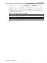
Table 3-4
DIP Switch Positions in the Sync-Transceiver
Switch
Position
S1/1
Application-specific (light idle state mode as per the system configuration at the optical-fiber
input R1)
S1/2
Open
S1/3
Closed (channel pairing mode)
S1/4
Open
3.5
Application Examples
3.5 Synchronizing up to 20 SIPROTEC 3 Devices
Accessories, Sync Transceiver, Optical/Electrical Converter for Time Synchronization, Manual
29
C53000-G9050-C168-1, Edition 09.2019


