Electrical Connection
Auxiliary Voltage X2
Connect the auxiliary voltage using the terminals X2 on the underside of the device. The assignment of the
terminals is printed on the front of the device, see
2.2.1 Arrangement of the Connections
. As the device does
not have its own switch, this must be installed externally.
Terminals:
Conductor cross-section (single wire or stranded wire) 1.5 mm
2
to 2.5 mm
2
Recommended stripping length
8 mm to 10 mm (with crimp terminals)
i
i
NOTE
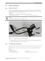
The connection lines must have a minimum length of 50 cm.
[sc_cabel_ferro, 1, --_--]
Figure 4-1
Wrapping the Ferrite Core and Binding the Cables
²
Wrap the connection lines for L and N each 4x and next to one another around the supplied ferrite core.
²
Fix the input and output lines in position using cable ties.
Fault-Signaling Connection X7
The terminals X7 are equipped with an isolated contact that is automatically closed by the device in case of an
error.
The assignment of the terminals is printed on the front of the device, see
2.2.1 Arrangement of the Connec-
Terminals:
Fault-signaling connection
Max. 2.5 mm
2
Recommended stripping length
8 mm to 10 mm (with crimp terminals)
4.2
4.2.1
4.2.2
Assembly and Commissioning
4.2 Electrical Connection
Accessories, Sync Transceiver, Optical/Electrical Converter for Time Synchronization, Manual
39
C53000-G9050-C168-1, Edition 09.2019


