861-9601.9 • INSTALLATION AND OPERATING INSTRUCTIONS • 8DA10 • Revision 11
63/214
Installation
Preparing
busbar assembly on
the right end panel
This operation is
only
performed if there is a horizontal flange cover available on the busbar
housing of the right end panel.
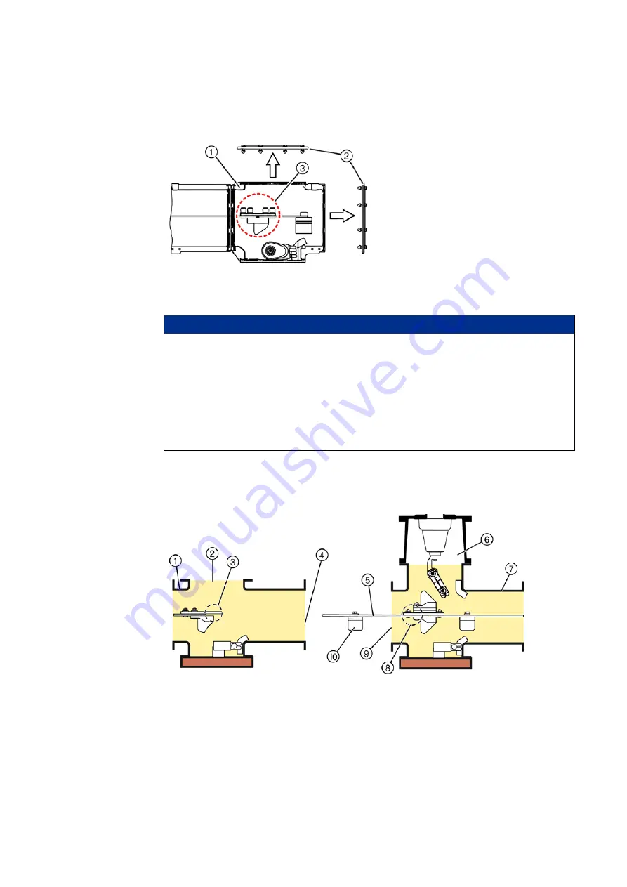
➭ Remove all flange covers ② from the assembly openings of the short busbar housing ① .
➭ If required, remove the protective caps from the bolts at the busbar ends, and loosen the
bolts.
Re-assembling the
busbars
Before starting to interconnect the panels, the busbar sections of the fixed-mounted panel
must be re-assembled to the panel to be lined up. The illustrations below show the state after
re-assembling.
Fig. 42:
Short busbar housing in right end panel
of fixed-mounted switchgear assembly
①
Short busbar housing
②
Flange cover
③
4 bolts with protective caps at the joint of
the busbar ends
NOTICE
This operation is only performed if one of the following components is mounted on the
busbar housings of the panel to be lined up.
In these cases, the busbar joints are not accessible anymore after the panels have been
interconnected.
- Disconnectable busbar connection
- Disconnectable busbar voltage transformer
- Make-proof busbar earthing switch
- top-mounted busbar sectionalizer
Fig. 43:
Busbar re-assembled (example 1250 A)
①
Short busbar housing of the fixed-mounted
panel
⑥
Transformer connection housing for the
contact of the busbar voltage transformer
②
Assembly openings (horizontal flanges)
⑦
Busbar housing of the panel to be lined up
③
Joint of the fixed-mounted panel
⑧
Joint of the panel to be lined up
④
Vertical flanges of the fixed-mounted panel
⑨
Vertical flanges of the panel to be lined up
⑤
Busbar
⑩
Busbar support


