6
A5E00721185
Read and understand these instructions before installing, operating, or
maintaining the equipment.
Reliable functioning of the equipment is only ensured with certified
components.
.
The 8MF2000 cabinet system is suited for the installation of electronic and
conventional control and automatic control systems, measuring and process
control systems, safety systems, communication systems as well as low-voltage
switchgear system devices and equipment.
The design, for example, makes it possible to quickly and efficiently install:
• Module racks for 19 " built-in components of different types of industrial
electronic systems
• Branch groups for energy distribution
The switchgear cabinets are delivered completely assembled.
An equipped cabinet with an overall weight of 500 kg can be lifted by crane
without requiring any further measures. Another 200 kg of equipment can be
added at the installation location.
For transport, the switchgear cabinet can be provided with transport eyebolts.
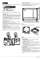
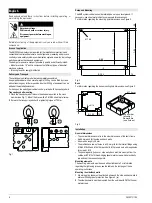
Transport eyebolt mounting
1
Place the transport eyebolt brace in the adequate position in the cross
member (see Fig. 1). Mount the brace with a PM 5x10 sheet metal screw.
2
Screw in the transport eyebolt with a tightening torque of 70 Nm.
Fig. 1
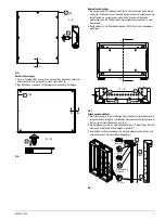
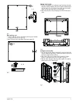
The 8MF system cabinets should preferably be set up on level ground. If
necessary, use sheet metal strips to compensate for unevenness.
For information regarding the mounting point dimensions, see Figure 2.
Fig. 2
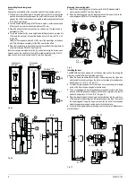
Base
For information regarding the base mounting hole dimensions, see Figure 3.
Fig. 3
General dimensions
• The nominal dimensions refer to the outer dimensions of the basic frame
• Add 9 mm each for the side and back walls.
• A door adds roughly 26 mm.
• The profiles have rows of holes in a 20-mm grid for the interior fittings using
M 8x15, M 8x25 and M 6x15 draw-in bolts, M 5 press-in nuts or through-holes
for screws = M 8
• The paneling parts (top cover, side walls, back wall) are mounted from the
outside with PM 5x10 thread-ridging sheet metal screws which electrically
join and seal the connection points.
Mounting elements
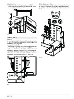
The mounting elements must be used without lubricants. For information
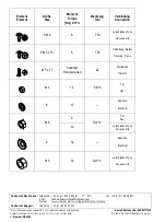
regarding the tightening torques, see the table on the last page of these
operating instructions.
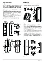
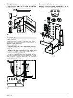
Mounting the side/back walls
1
9x4 mm sealing tape must be attached all around the side and back walls to
achieve IP54 degree of protection. See Figure 4 (
a
).
2
The side/back walls must be mounted from the outside with PM 5x10 sheet
metal screws.
English
Hazardous voltage.
Will cause death or serious injury.
Disconnect power before working on
equipment.
Areas of application
Delivery and Transport
!
Setup and Mounting
Installation
7
7
%
%
X
%
7
PP
DEQHKPEDU
5HPRYDEOH
DOOVHLWLJ
RQDOOVLGHV


