8
A5E00721185
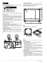
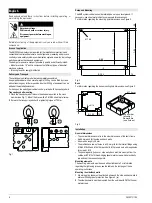
Assembling the cabinet groups
Caution
Observe the accessibility of the connection points of the mounting version!
1
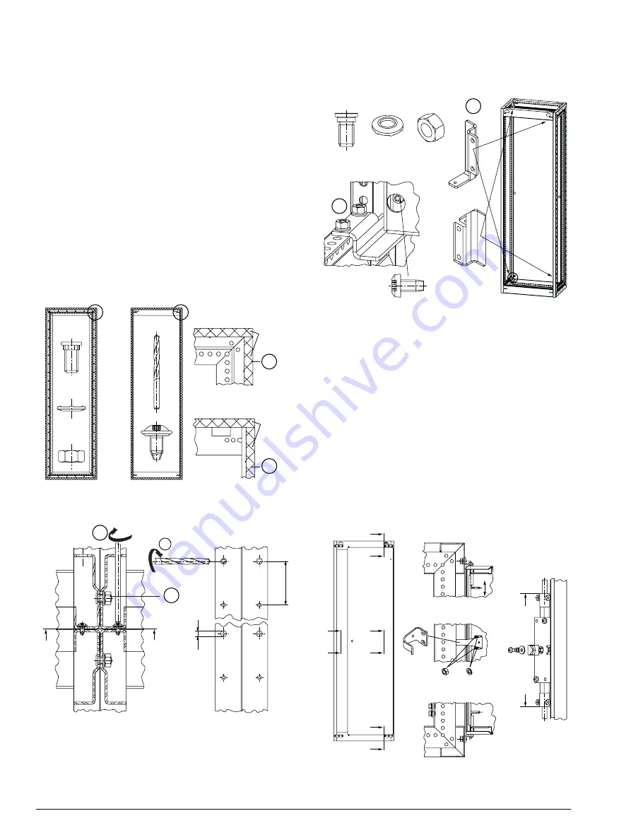
When two or more cabinets are to be joined together, 20x1 mm sealing tape
must be attached all around between the outer row of holes and the frame
edge on one of the frame surfaces to be joined to achieve degree of protection
IP54. See Figure 8a
(a)
.
2
Join the frames laterally using M 8x15 draw-in bolts, 8 contact washers and
M 8 nuts with a maximum mounting distance of 500 mm.
3
Figure 8b shows the frame connection in a cabinet row. The seal shown is
necessary for IP54.
4
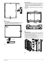
To join two cabinets of the same height and width back-to-back, enlarge 6 to
10 holes in the back wall of one of the frames from Ø 4.5 mm to Ø 7.0 ± 0.3
(Figure 8b).
Observe the maximum distance S of 500 mm of the mountings on the back
wall. This distance is necessary for the IP54 seal to take effect.
5
Place the frames back-to-back close to each other and bolt them together with
sheet metal screws PM 5x10. See Figure 8b.
Bolt the cross members together at the top and bottom using the lateral round
holes as well as the center hole (from 900 mm cabinet widths) using M 8x15
draw-in bolts, 8 contact washers and M 8 nuts. See Figure 8b.
Fig. 8a
Fig. 8b
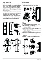
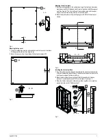
Mounting the mounting plate
1
Mount the 4 mounting angles to the frame with M 8x15 threaded bolts, 8
contact washers and M 8 nuts. See Figure 9.
2
Place the mounting plate onto the lower angles and first mount them to the
upper angles using PM 6x12 thread-ridging screws.
Fig. 9
Installing the door
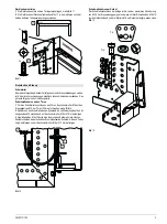
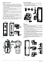
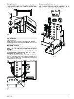
The 8MF2000 door has 3 stop points on the hinge side and 3 on the locking rod
side to be used as left-side or right-side end stops.
1
When the doors are delivered unmounted, the door angle on the hinge side
and the steel bracket mounting on the lock must be taken into consideration.
See Sections “L-L” and “I-I” in Figure 10.
2
To install the fully equipped door, mount the 4 door support angles for single
doors or the 6 door support angles for double doors.
3
The 4, or respectively 6, door support angles are each mounted to the frame
with one M 8x15 threaded bolt and one M 8 nut hat is secured with a contact
washer. See Sections “H-H” and “K-K” in Figure 10.
4
Place the lower hinge bolt of the single door/double door into the outer hole
of the lower door support angle on the respective end-stop side. Then retract
the upper hinge bolt using the hinge lever, position the bolt at the respective
hole in the upper door support angle and let it click into place.
6
For information regarding door grounding, see the chapter on “Measures to
protect the door”.
Fig. 10
[
<
=
[
s
0[
0
%DFN
OHIWULJKW
'HWDLO<
'HWDLO=
5¾FNVHLWH
OLQNVUHFKWV
D
D
(
(
((
s
6
0[
[
0[
[
[
0
[
;
'HWDLO;
.
.
++
..
+
+
/
/
//
[
[0
,
,
,,
0[
PD[


