background image


10. Maintenance. 

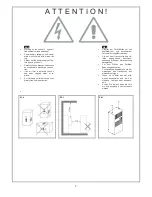
Caution! Before embarking on any mainte-
nance work, switch current off to the enclo-
sure. 

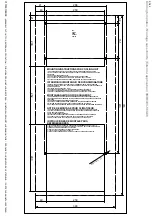
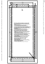
The cooling unit is the low maintenance 

type so no filter change is required. The only 
jobs that need doing are the internal compo-
nents with compressed air at a maximum pres-
sure of 4 bar (figure 

F.34.1

) and which should 

be checked regularly. 
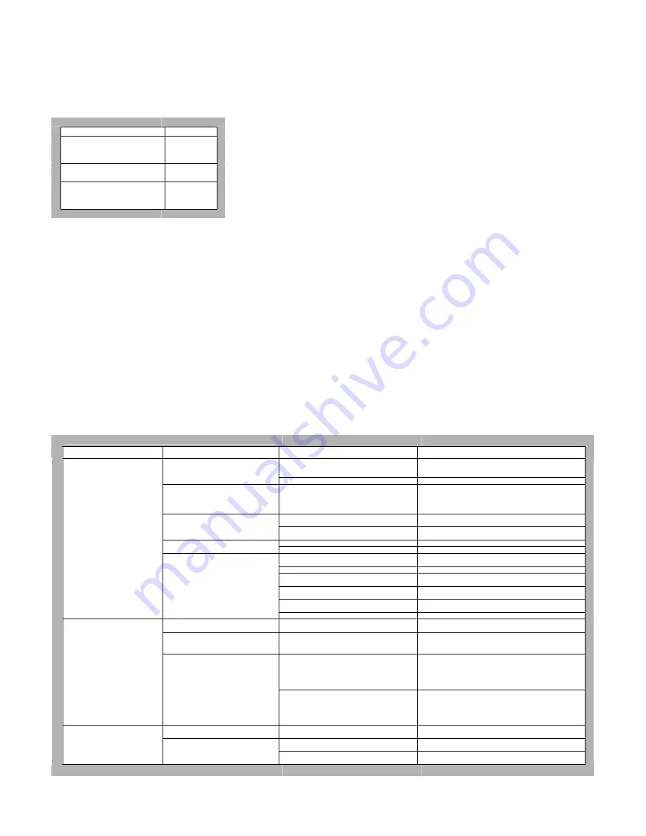


Job


Frequency


Check the external air heat 
exchanger and clean if 
necessary


Every 3 
months


Check effectiveness of the 
condensate discharge


Every 3 
months


Check the fans for any 
overheating or excessive 
vibrations


Every 6 
months


Any repairs that may need doing must only be 
done by specialised and authorised personnel 
and using original spare parts only. 
 

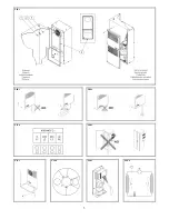
11. Technical information. 
11.1 Operating principle. 

The cooling unit for electric enclosures works 
on the basis of a refrigeration circuit consisting 
of four main components: compressor, evapo-
rator, condenser and expansion device (figure 

F.36.0

). The circuit is hermetically sealed and 

the refrigerant circulates inside


it. The refriger-

ant used is R134a, chlorine free and harmless 
for the ozone layer. The unit is divided into two 
hermetically separated sections where the am-
bient air and enclosure air do not come into 
contact with one another and are treated sepa-
rately. The compressor (CP) compresses the 
refrigerant and takes it to a high pressure and 
high temperature. The compressor then pushes 
the refrigerant through a heat exchanger coil, 
called condenser (C), where it is cooled by am-
bient air thus passing from the gas to the liquid 
state. At the liquid state it then passes through 
the capillary (EXP) and as it is at a much lower 
pressure, nebulizes at the outlet. It is then re-
ceived by the heat exchanger coil, called 
evaporator (E), by means of which it absorbs 
heat from the enclosure air and passes from a 
liquid state to gas. The enclosure is cooled 

down in this manner. The gas is then drawn 
back into the compressor and the above de-
scribed cycle is repeated.


11.2 Safety devices. 

The refrigeration circuit is fitted with a high 
pressure safety switch P (figure 

F.36.0

) set at 

maximum cooling unit working pressure. If the 
threshold is exceeded, the pressure switch 
stops the compressor working. It is the auto-
matically resettable type. The fans and com-
pressor have a thermal cut-out switch inside 
that stops them in the case of anomalous over 
temperatures.


11.3 Disposal. 
Caution! The cooling unit contains R134a re-
frigerant and small quantities of lubricating 
oil

. These substances pollute and must not be 

dumped. Replacement, repairs and final dis-
posal must be seen to by experts. 
 

NOTE 

Keep the documentation in a dry place. 
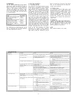
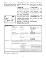


12. Troubleshooting


Malfunction


Conditions


Causes


Remedy


The temperature inside the enclosure is lower than 
what is set on the adjustment thermostat.


This is not a malfunction of the cooling unit. To verify functioning 
when testing, lower the thermostat setting until the compressor 
and external fan start working and then reset the thermostat.


The internal fan works, the external fan and 
compressor do not work.


The adjustment thermostat has failed


Change the adjustment thermostat


No component works


No electricity getting to the unit.


This is not a malfunction of the cooling unit. 


Make sure the power cable has been connected well to the 

terminals. 


Check that the cubicle doors and switches are closed


Cooling unit empty of fluid


Call a refrigeration expert or the Manufacturer’s Technical Assis-
tance Service


Compressor, external and internal fan work


Compressor mechanical failure


Call a refrigeration expert or the Manufacturer’s Technical Assis-
tance Service


Internal fan capacitor failed


Change the internal fan’s capacitor


Compressor and external fan work, internal 
fan does not work


Internal fan failed


Change the internal fan


Compressor’s amperometric protector failed (external 
to the compressor, where present)


Change the amperometric protector


Relay or PTC for compressor starting failed


Change the relay or PTC for compressor starting


Capacitor for compressor starting failed (where pre-
sent)


Change the capacitor for compressor starting


Compressor motor electrical failure


Call a refrigeration expert or the Manufacturer’s Technical Assis-
tance Service


High pressure safety switch failed


Call a refrigeration expert or the Manufacturer’s Technical Assis-
tance Service


It fails to cool


External and internal fan work, compressor 
does not work


Compressor contactor failed (where present)


Change the contactor


External and internal fans work, compressor 
works all the time


Cooling unit under sized for the heat dissipated inside 
the enclosure


Change the cooling unit with another of greater capacity


Inside fan works, external fan and compres-
sor work irregularly


Insufficient gas in the cooling unit


Call a refrigeration expert or the Manufacturer’s Technical Assis-
tance Service


High pressure safety switch triggered: 


Ambient temperature over the maximum work-

ing limit 


Heat exchanger coil (condenser) either dirty or 

clogged


Ventilate the premises where the enclosure is installed to 

keep ambient temperature lower. 


Clean the exchanger with compressed air and detergent


It is not cooling enough


External and internal fans work, compressor 
works irregularly


Thermal protector inside the compressor triggered: 


Ambient temperature over the maximum work-

ing limit 


Heat exchanger coil (condenser) either dirty or 

clogged


Ventilate the premises where the enclosure is installed to 

keep ambient temperature lower. 


Clean the coil with compressed air and detergent


Enclosure door open


Too much ambient air inside the enclosure


This is not a malfunction of the cooling unit. Close the enclosure 
door or disable the cooling unit


Enclosure protection level is below IP54


This is not a malfunction of the cooling unit. Seal enclosure open-
ings, e.g. for passage and upward path of wires


Too much condensate forming


Enclosure door closed


The enclosure/cooling unit connecting seal has been 
fitted incorrectly


Check seal and remedy


Summary of Contents for 8MR6423-5EG04

Page 1: ...operation and maintenance manual Montage Betriebs und Wartungsanleitung Air conditioner for electric enclosure Schaltschrank Kühlgerät 8MR6423 5EG04 8MR6423 5EG06 8MR6423 5EG08 A T T E N T I O N Read carefully and completely before installation Keep the manual until unit decommissioning Lesen Sie das vorliegende Handbuch in allen seinen Teilen aufmerksam durch bevor das Gerät installiert wird Das ...

Page 2: ...ts and outlets must be com pletely free from obstruction DEU Arbeiten am Gerät dürfen nur von qualifiziertem und autorisiertem Personal durchgeführt werden Die auf dem Typenschild des Ge rätes angegebene Anschluss spannung muss der Netzspannung entsprechen Vor dem Öffnen des Gerätes Spannung abschalten Für Kondenswasserablass die An weisungen des Handbuchs auf merksam befolgen Wenn ein Luftfilter ...

Page 3: ...DEU Nutzkühlleis tung Versorgungs spannung Abmessungen BxHxT Höchststrom Anlauf strom Vorsiche rungT Nennleistung Einschalt dauer Kältemittel zul Be triebsüber druck Schalt schrank temperatur bereich Temperatur regelung Umge bungs temperatur bereich Schutzart Innenkreis lauf Schutzart Außen kreislauf Geräusch pegel Gewicht Konformität EN814 EN814 A35 A35 A35 A50 A35 A35 A35 A50 R134a W W V Hz mm A...

Page 4: ...4 F 13 1 Dimensions Abmessungen 8MR6423 5EG04 8MR6423 5EG06 8MR6423 5EGO08 External Außenmontage Semi recessed Teileinbau ...

Page 5: ...5 F 19 1 F 22 1 F 25 1 F 27 0 F 28 1 F 31 1 F 33 0 F 34 1 F 36 0 ...

Page 6: ...phe nomenon of the cooling unit The condensate is taken outside through a hose at the bottom of the cooling unit The transparent plastic hose supplied with the unit must be connected to this discharge figure F 31 1 This plastic hose can be connected to another one with the same diameter to carry the con densate to another point so when it is dis charged it is where there can be no slipping hazard ...

Page 7: ...mostat setting until the compressor and external fan start working and then reset the thermostat The internal fan works the external fan and compressor do not work The adjustment thermostat has failed Change the adjustment thermostat No component works No electricity getting to the unit This is not a malfunction of the cooling unit Make sure the power cable has been connected well to the terminals...

Page 8: ...kschlauch kann mit einem weiteren Schlauch desselben Durchmessers verbunden werden um das Kondenswasser so abzufüh ren dass niemand darauf ausrutschen kann Das Kondenswasser muss hinderungsfrei ab laufen können Der Ablaufschlauch sollte nicht mehr als 0 5 m horizontal oder in Gegennei gung verlaufen ebenso sollte die Bildung von ungewollten Bögen vermieden werden Abb F 22 1 Das Schlauchende des Ko...

Page 9: ...ieb gesetzt werden daraufhin den Eichpunkt wieder zurückstellen Innenventilator funktioniert Außenventilator und Kältemittelverdichter nicht Einstellthermostat defekt Einstellthermostat austauschen Kein Element funktioniert Gerät ohne Spannung Keine Gerätestörung Kontrollieren dass das Versorgungskabel fest mit den Klemmen verbunden ist Kontrollieren dass Schranktüren und Schalter geschlos sen sin...

Page 10: ... Startrelais K3 alarm relay K3 Alarmrelais MT1 compressor MT1 Kältemittelverdichter MT2 evaporator fan MT2 Verdampferventilator MT3 condenser fan MT3 Verflüssigerventilator P NTC probe P Sonde NTC S adjustment thermostat S Thermostat S3 digital input for the alarm external signalling S3 Digitaleingang für Außenalarm Signalisierung T autotransformer T Spartransformator X terminal board X Klemmbrett...

Page 11: ...ter 20 Filtertrockner 21 assembly accessories kit 21 Beutel mit Montagezubehör 34 compressor starter 34 elektr Starteinheit Kompressor 35 evaporator fan capacitor 35 elekt Kondensator Verdampferlüfter 36 condenser fan capacitor 36 elekt Kondensator Verflüssigerlüfter ENG DEU When ordering the fol lowing informations are essential Bei einer Bestellung bitte die folgenden In formationen unbedingt an...

Page 12: ...12 8MR6423 5EG06 8MR6423 5EG08 ...

Page 13: ...N ANKÖRNEN BOHREN UND ENTGRATEN 4 AUSSCHNITTE EINSCHLIEßLINCH DER LINIENBREITE AUSSCHNEIDEN UND ENTGRATEN 5 DICHTUNG ABLÄNGEN UND AUF DIE RÜCKSEITE DES GERÄTES AUFKLEBEN 6 KÜHLGERÄT MIT BEILIEGENDEN GEWINDESTIFTEN MUTTERN UND ZAHNSCHEIBEN BEFESTIGEN NOTICE DE MONTAGE POUR CLIMATISEUR 1 VERIFIER LES DIMENSIONS DU GABARIT DE PERÇAGE AVANT DE PERFORER ET COUPER 2 COLLER LE GABARIT DE PERÇAGE AVEC RUB...

Page 14: ...OHRUNGEN ANKÖRNEN BOHREN UND ENTGRATEN 4 AUSSCHNITTE EINSCHLIEßLINCH DER LINIENBREITE AUSSCHNEIDEN UND ENTGRATEN 5 DICHTUNG ABLÄNGEN UND AUF DIE RÜCKSEITE DES GERÄTES AUFKLEBEN 6 KÜHLGERÄT MIT BEILIEGENDEN GEWINDESTIFTEN MUTTERN UND ZAHNSCHEIBEN BEFESTIGEN NOTICE DE MONTAGE POUR CLIMATISEUR 1 VERIFIER LES DIMENSIONS DU GABARIT DE PERÇAGE AVANT DE PERFORER ET COUPER 2 COLLER LE GABARIT DE PERÇAGE A...

Page 15: ... UND ENTGRATEN 4 AUSSCHNITTE EINSCHLIEßLINCH DER LINIENBREITE AUSSCHNEIDEN UND ENTGRATEN 5 DICHTUNG ABLÄNGEN UND AUF DIE RÜCKSEITE DES GERÄTES AUFKLEBEN 6 KÜHLGERÄT MIT BEILIEGENDEN GEWINDESTIFTEN MUTTERN UND ZAHNSCHEIBEN BEFESTIGEN NOTICE DE MONTAGE POUR CLIMATISEUR 1 VERIFIER LES DIMENSIONS DU GABARIT DE PERÇAGE AVANT DE PERFORER ET COUPER 2 COLLER LE GABARIT DE PERÇAGE AVEC RUBAN ADHESIF SUR LE...

Page 16: ...AUSSCHNEIDEN UND ENTGRATEN 5 DICHTUNG ABLÄNGEN UND AUF DIE RÜCKSEITE DES GERÄTES AUFKLEBEN 6 KÜHLGERÄT MIT BEILIEGENDEN GEWINDESTIFTEN MUTTERN UND ZAHNSCHEIBEN BEFESTIGEN ISTRUZIONI DI MONTAGGIO PER CONDIZIONATORE 1 PRIMA DI FORARE E RITAGLIARE VERIFICARE LE DIMENSIONI DELLA DIMA DI FORATURA 2 FISSARE LA DIMA DI FORATURA CON NASTRO ADESIVO SULLE PARETI LATERALI OPPURE SULLA PORTA DELL ARMADIO 3 BU...

Page 17: ...BEN 3 BOHRUNGEN ANKÖRNEN BOHREN UND ENTGRATEN 4 AUSSCHNITTE EINSCHLIEßLINCH DER LINIENBREITE AUSSCHNEIDEN UND ENTGRATEN 5 DICHTUNG ABLÄNGEN UND AUF DIE RÜCKSEITE DES GERÄTES AUFKLEBEN 6 KÜHLGERÄT MIT BEILIEGENDEN GEWINDESTIFTEN MUTTERN UND ZAHNSCHEIBEN BEFESTIGEN NOTICE DE MONTAGE POUR CLIMATISEUR 1 VERIFIER LES DIMENSIONS DU GABARIT DE PERÇAGE AVANT DE PERFORER ET COUPER 2 COLLER LE GABARIT DE PE...

Page 18: ...SCHLIEßLINCH DER LINIENBREITE AUSSCHNEIDEN UND ENTGRATEN 5 DICHTUNG ABLÄNGEN UND AUF DIE RÜCKSEITE DES GERÄTES AUFKLEBEN 6 KÜHLGERÄT MIT BEILIEGENDEN GEWINDESTIFTEN MUTTERN UND ZAHNSCHEIBEN BEFESTIGEN ISTRUZIONI DI MONTAGGIO PER CONDIZIONATORE 1 PRIMA DI FORARE E RITAGLIARE VERIFICARE LE DIMENSIONI DELLA DIMA DI FORATURA 2 FISSARE LA DIMA DI FORATURA CON NASTRO ADESIVO SULLE PARETI LATERALI OPPURE...

Reviews: